Good Brown Gravy
Junior Member level 1

- Joined
- Feb 23, 2008
- Messages
- 16
- Helped
- 1
- Reputation
- 2
- Reaction score
- 0
- Trophy points
- 1,281
- Activity points
- 1,423
Hi Guys,
I am working on a preamp that has a bit of unconventional functionality. Below is the part of the preamp that I have got working to date.

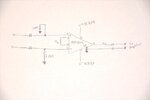
An audio signal comes into the input on the left of the schematic, passes through a couple of DC protection caps, and passes into the SSM2019 preamp. Resistor Rg controls the gain and for now I have pot a potentiometer in its place. The signal is amplified and then outputs to my audio amp that outputs to my headphones.
The unconventional part is what I propose below.

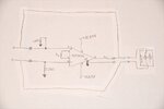
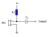
My audio amp, shown to the right on the schematic, has the ability to push a +15V to -15V bias back down the input line. This voltage is used to power small microphones like this. I want to be able to pass this voltage back around the preamp to a microphone that is waiting down the line. However, when I arrange the jumpers as shown and push dc bias down the line, the microphone seems to come on but any audio is really, really, really, low. The only way I know it's working a little bit is because when I touch the mic, I hear a little response but no voice like when the jumpers are removed and the mic is powered externally.
The only other thing I'm doing is using a TC7660 for the negative rail of my preamp.
I've been so pleased with how the preamp works by itself and would really like to add this last piece of functionality. Thank you for any help you guys might be able to provide. Have a great day!
Jason
I am working on a preamp that has a bit of unconventional functionality. Below is the part of the preamp that I have got working to date.

An audio signal comes into the input on the left of the schematic, passes through a couple of DC protection caps, and passes into the SSM2019 preamp. Resistor Rg controls the gain and for now I have pot a potentiometer in its place. The signal is amplified and then outputs to my audio amp that outputs to my headphones.
The unconventional part is what I propose below.

My audio amp, shown to the right on the schematic, has the ability to push a +15V to -15V bias back down the input line. This voltage is used to power small microphones like this. I want to be able to pass this voltage back around the preamp to a microphone that is waiting down the line. However, when I arrange the jumpers as shown and push dc bias down the line, the microphone seems to come on but any audio is really, really, really, low. The only way I know it's working a little bit is because when I touch the mic, I hear a little response but no voice like when the jumpers are removed and the mic is powered externally.
The only other thing I'm doing is using a TC7660 for the negative rail of my preamp.
I've been so pleased with how the preamp works by itself and would really like to add this last piece of functionality. Thank you for any help you guys might be able to provide. Have a great day!
Jason


