Continue to Site

Welcome to EDAboard.com

Welcome to our site! EDAboard.com is an international Electronics Discussion Forum focused on EDA software, circuits, schematics, books, theory, papers, asic, pld, 8051, DSP, Network, RF, Analog Design, PCB, Service Manuals... and a whole lot more! To participate you need to register. Registration is free. Click here to register now.

Hartley Oscillator amplitude problem

Status
Not open for further replies.

TMTYB

Newbie level 2
Joined
Feb 3, 2010
Messages
2
Helped
0
Reputation
0
Reaction score
0
Trophy points
1,281
Location
South Africa
Activity points
1,293
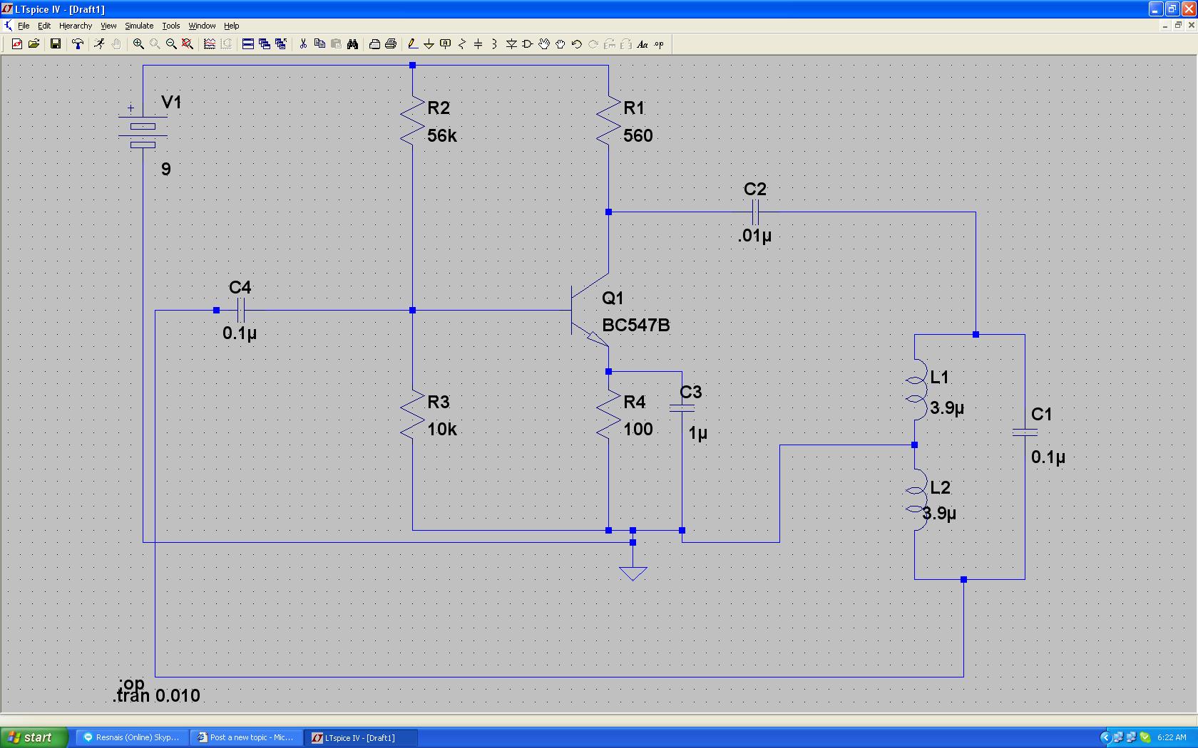
I have used LT spice IV (https://www.linear.com/designtools/software/ltspice.jsp)
to simulate the attached circuit, and it works perfectly.


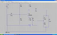
But when I build the circuit on a bread board, Everything works okay, except that the amplitude is allot smaller than expected (on simulation 10V p-p.. Built circuit 180mV p-p).

I have checked the built circuit for errors such as wrong pins in wrong places. ect. but havent found any fault there.

I need a 4Vp-p signal output.

Help would be appreciated.
Tnx.
 

Did you checked you bias current level??

Second, from your schematic I just see ideal component in the LC tank and everwhere (except the transistor).
So the Q of your tank is basically infinite (zero loss), if you include the losses you will see a much smaller amplitude.
 

I am not sure of the reason for your problem, but a few comments:

1. I think the Hartley has a tapped inductor, nut I am not sure. You have drawn it as two separate inductors. I cannot see any mutual coupling.

2. the inductors are very small and the capacitors very large for the frequency you are trying to achieve. Ideally you want to use NPO/COG capacitors in an oscillator or filter. I am guessing your capacitors will be something like X7R.

3. the inductors will have parasitic resistance which you have not taken into account in your simulation. The non-ideal characteristics of the capacitors have also been ignored.

My suggestion would be to first reduce your resonant capacitor and increase the inductors and use COG for the resonant capacitor. The coupling capacitors do not matter - just the resonant one (C1).

Keith.
 

Thank you all for the input, will try the info you gave me.
 

Status
Not open for further replies.

Part and Inventory Search

Welcome to EDABoard.com

Sponsor

Back
Top