Continue to Site

Welcome to EDAboard.com

Welcome to our site! EDAboard.com is an international Electronics Discussion Forum focused on EDA software, circuits, schematics, books, theory, papers, asic, pld, 8051, DSP, Network, RF, Analog Design, PCB, Service Manuals... and a whole lot more! To participate you need to register. Registration is free. Click here to register now.

hartley image reject structure

Status
Not open for further replies.

mujee

Member level 1
Joined
Feb 11, 2007
Messages
37
Helped
0
Reputation
0
Reaction score
0
Trophy points
1,286
Activity points
1,585
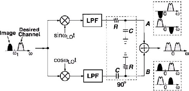
hey guys below is the block diagram of hartley image reject structure
what i want to know is why is only image signal inverted after the mixer stage..why doesnt wanted signal undergo inversion....please help me out as i cant understand the reason behind this

86_1178967880.jpg
 

Omega1 is the middle frequency, Image is lower it, and Desired Channel is Higher then Omega1.


Example for lower net on the picture:

For Image:
cos(Omega+Omega1)*t*cos(Omega*t)=0.5*[cos(Omega1*t)+cos(2*Omega*t+Omega1*t)]
here is no change of phase.

For Desired Channel:
cos(Omega-Omega1)*t*cos(Omega*t)=0.5*[cos(Omega1*t)+cos(2*Omega*t+Omega1*t)]
here is an inversion.
 

still not clear
btw i dont see any difference in equations that you wrote for the image and wanted channel
can anyone help please
 

Status
Not open for further replies.

Part and Inventory Search

Welcome to EDABoard.com

Sponsor

Back
Top