mcmsat13
Member level 5

- Joined
- Apr 24, 2013
- Messages
- 94
- Helped
- 4
- Reputation
- 8
- Reaction score
- 4
- Trophy points
- 1,288
- Activity points
- 2,292
Dear Edaboard engineers, I need help here! There is this Sine Wave Inverter circuit I am working on. I did not originate the circuit but instead with my own EDA software I redrawn it in a new way and better layout for easy understanding and I also corrected some mistakes in the the original circuit but still, I couldn't get it to work!
I get high frequency but it actually oscillated and produced output at very high frequency that gets the mosfets hot without a load! I don't want to just dump this circuit without showing you, my seniors in electronics project, the problem I am facing, to know if there is something you can do for it to work. If this circuit works I think it will be better than SG3524 circuit which I use in my current designs.
The circuit was design by one poster at some forum. The poster did not follow up the post to some extent where the thread died out. But I still believe that some senior designers here will point out some issues or correct some flaws in the design.
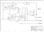
This is the picture of the original diagram.

Then the picture below is my own redrawn circuit.

Please examine this circuit and see if you can detect things that are wrong. I don't know if this circuit is originally correct.
Thanks in advance!
I get high frequency but it actually oscillated and produced output at very high frequency that gets the mosfets hot without a load! I don't want to just dump this circuit without showing you, my seniors in electronics project, the problem I am facing, to know if there is something you can do for it to work. If this circuit works I think it will be better than SG3524 circuit which I use in my current designs.
The circuit was design by one poster at some forum. The poster did not follow up the post to some extent where the thread died out. But I still believe that some senior designers here will point out some issues or correct some flaws in the design.
This is the picture of the original diagram.

Then the picture below is my own redrawn circuit.

Please examine this circuit and see if you can detect things that are wrong. I don't know if this circuit is originally correct.
Thanks in advance!
Last edited:

