DeepOne
Advanced Member level 2
- Joined
- Feb 26, 2011
- Messages
- 632
- Helped
- 99
- Reputation
- 200
- Reaction score
- 100
- Trophy points
- 28
- Location
- 45N39E, Russia
- Activity points
- 0
So, this is it.
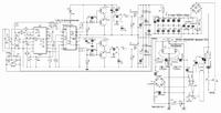
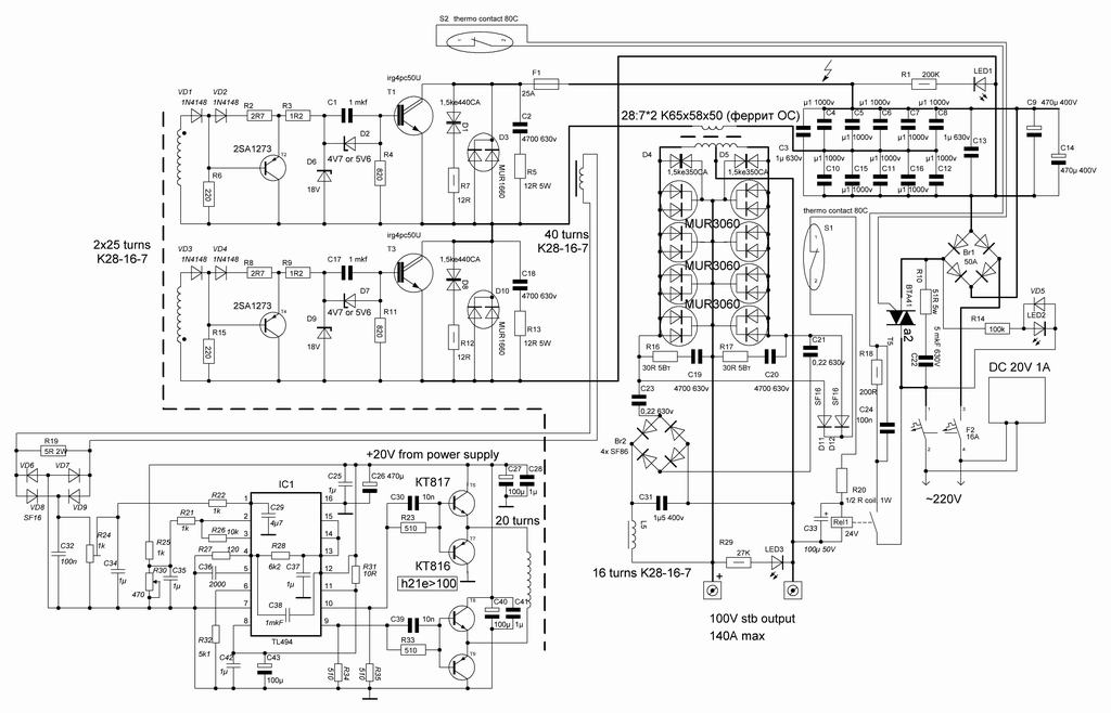
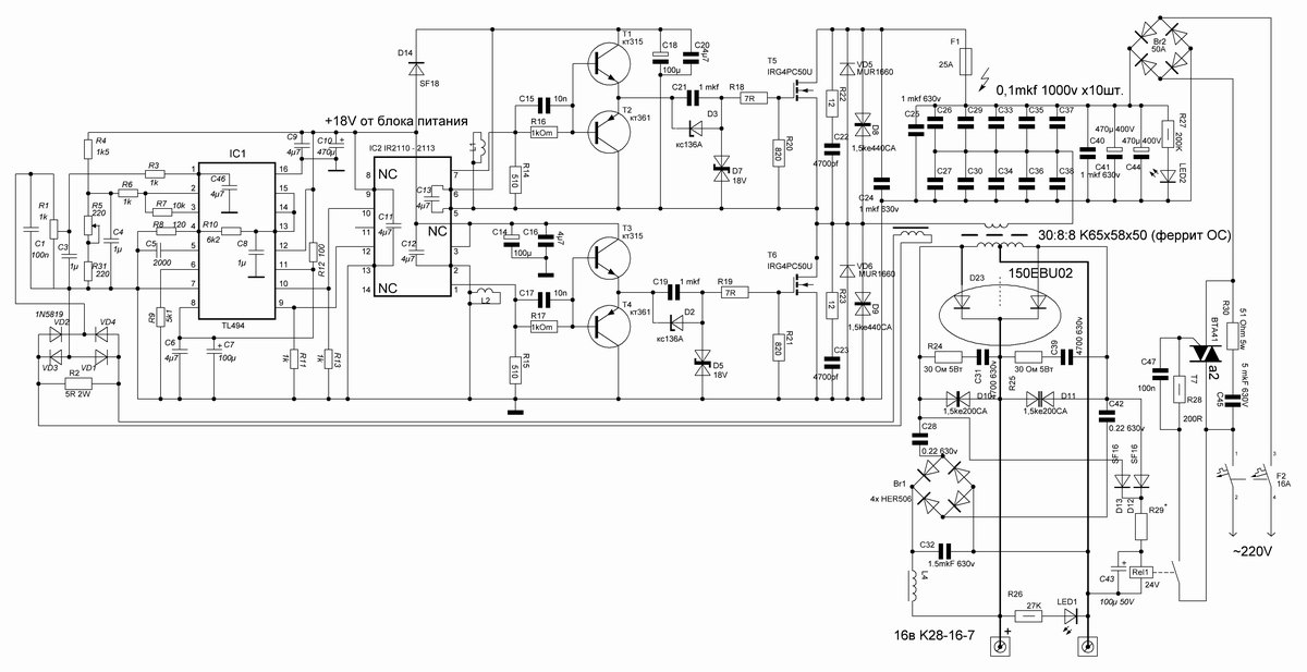
schematics

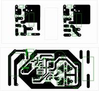
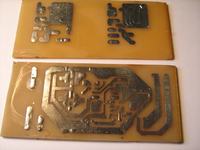
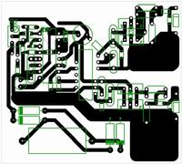
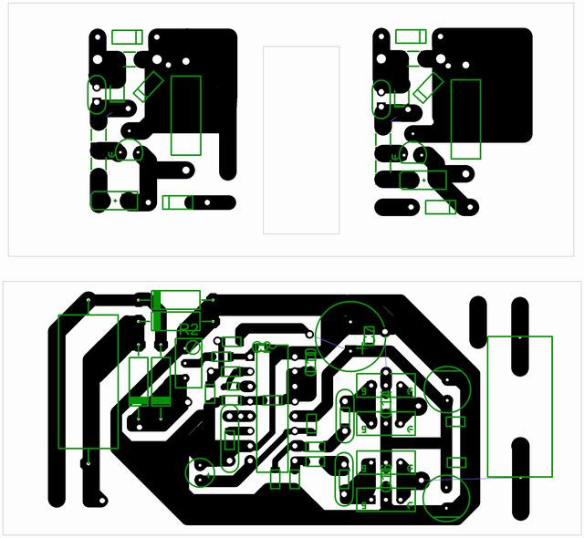
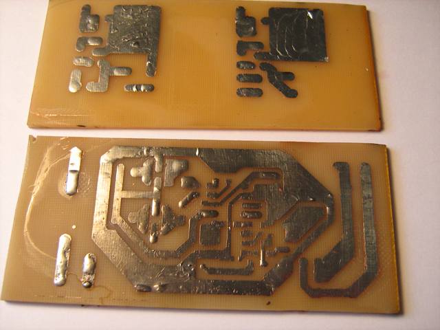
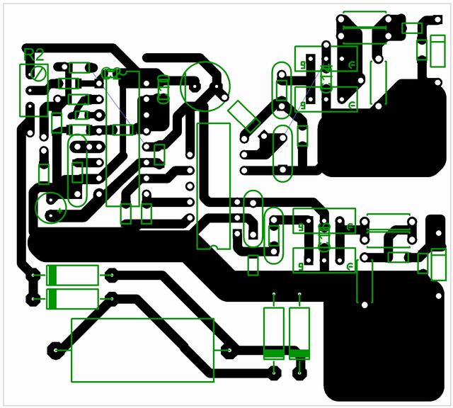
pcb
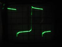
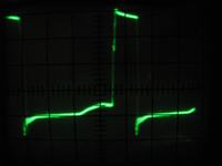
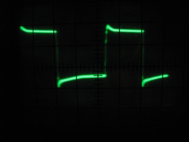
test

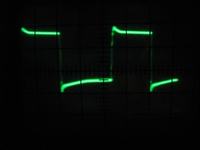
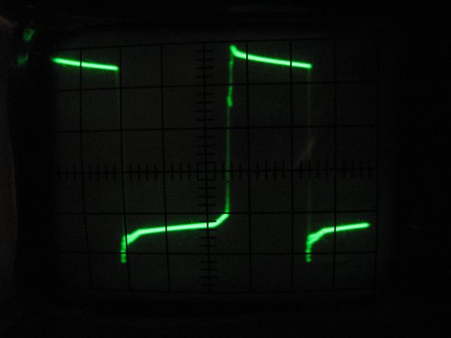
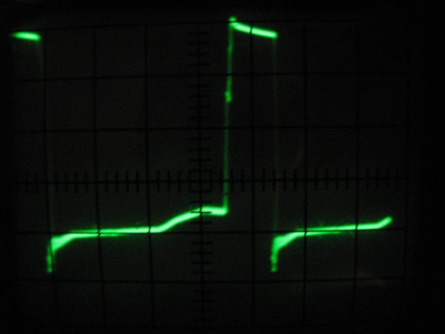
signal from IGBT gate, without power on collector, 5V/5mks/cell
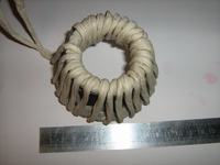
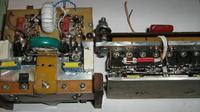
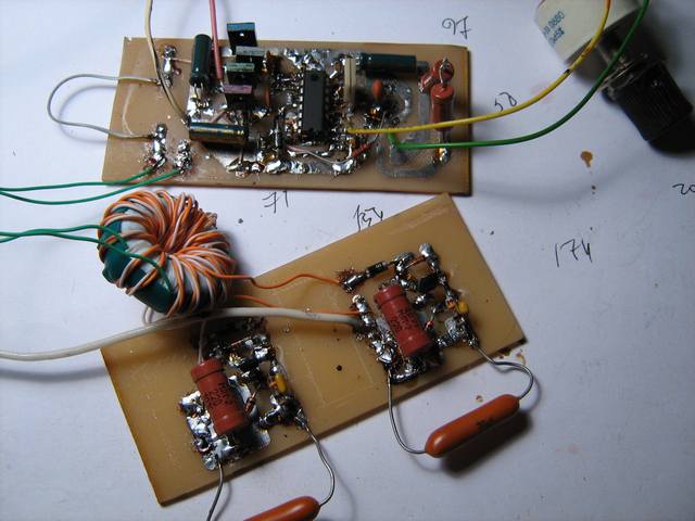
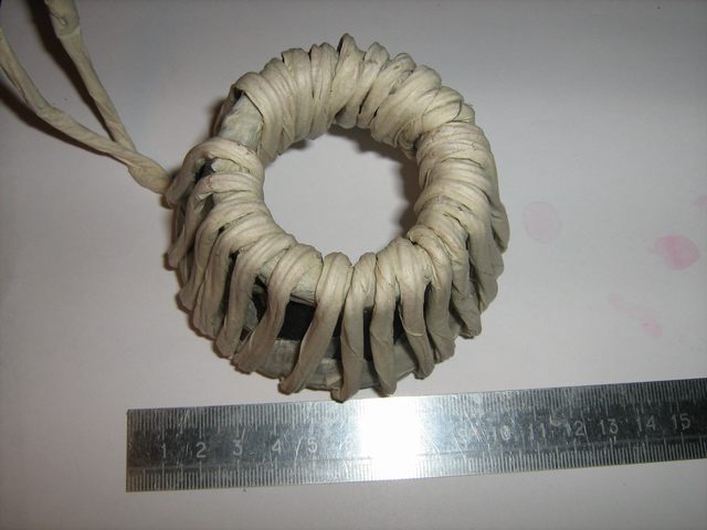
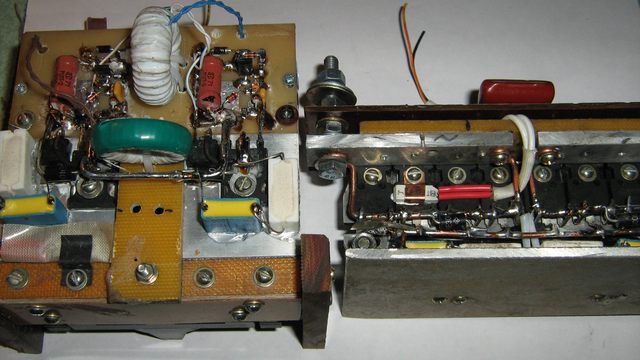
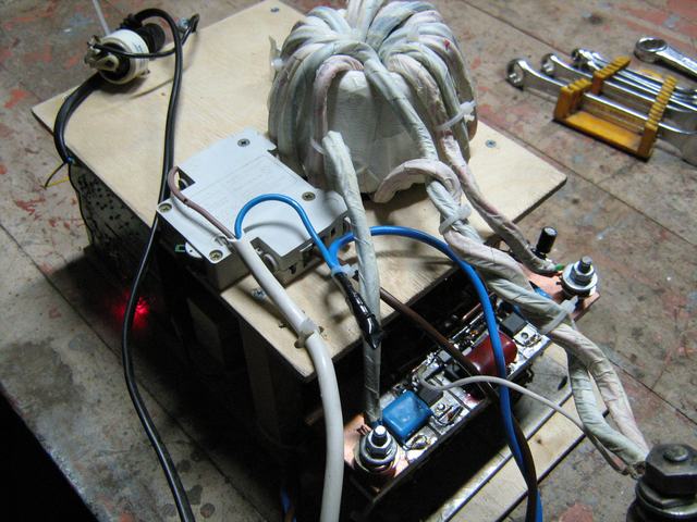
transformer, primary coil
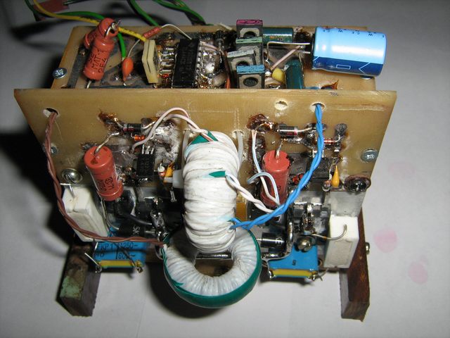
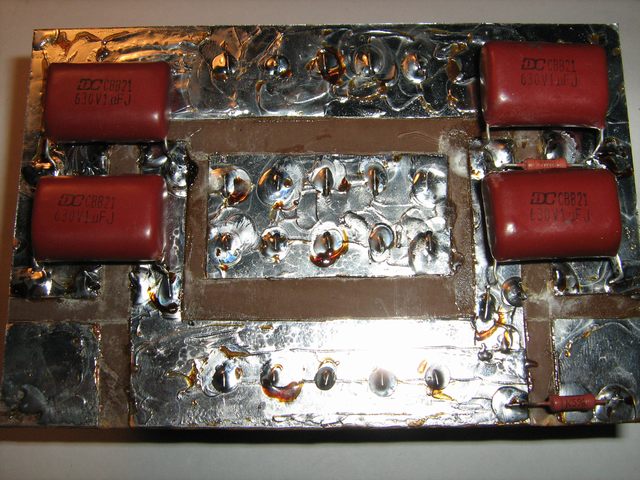
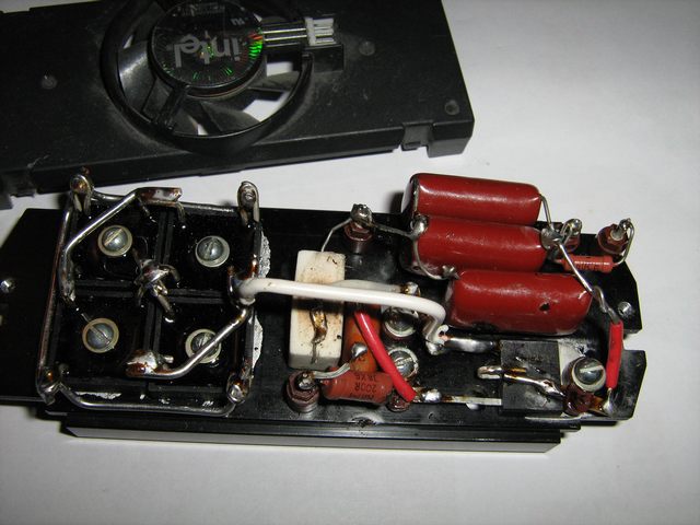
lower side rectifier
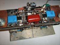
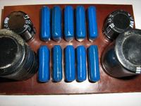
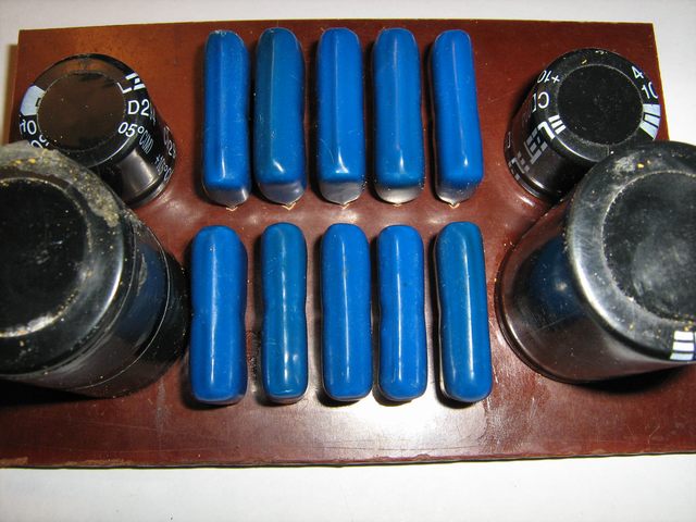
capacitors
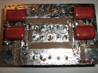
upper side rectifier, quad of BR1010 and start module withBTA41

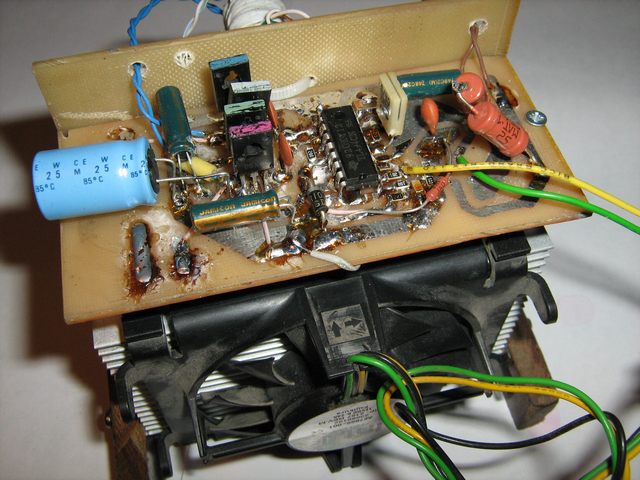
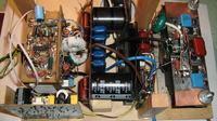
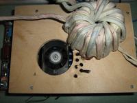
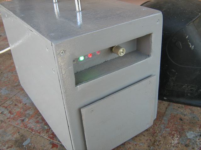
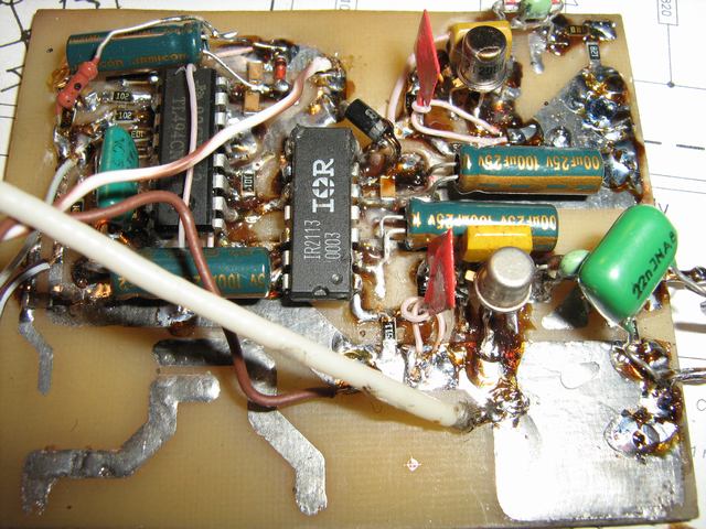
partly collected
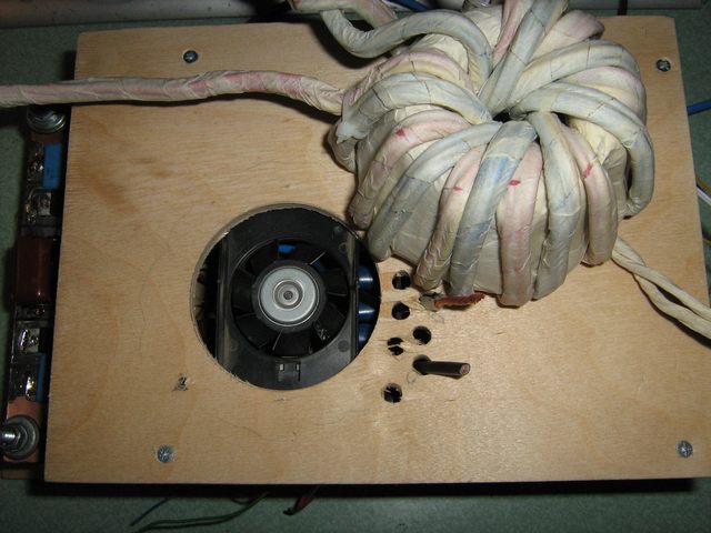
ventilator under main transformer
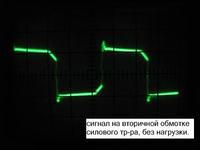
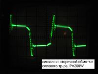
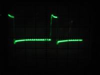
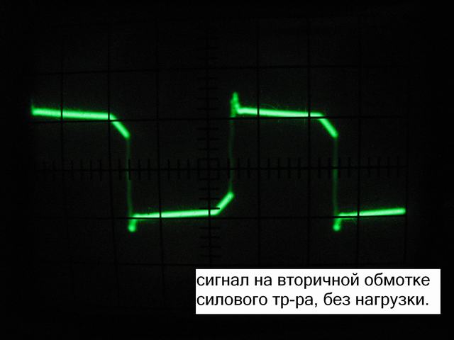
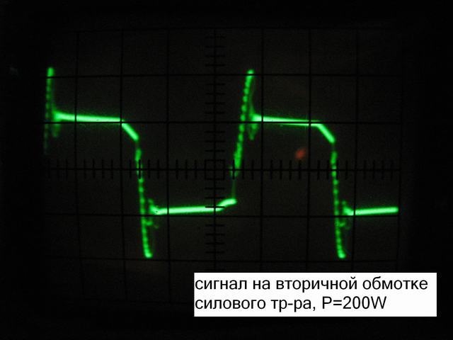
signal from second coil of main transformer
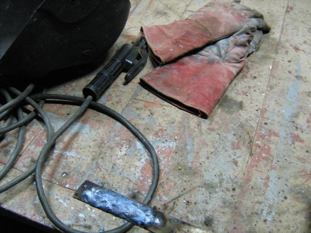
testing - incinerated two electrodes 3мм


Or possible do else on such scheme:
But it is necessary to make sure that minimum duration of the pulse it is enough for feeding upper shoulder of IR2110.

schematics
pcb
test
signal from IGBT gate, without power on collector, 5V/5mks/cell
transformer, primary coil
lower side rectifier

capacitors
upper side rectifier, quad of BR1010 and start module withBTA41
partly collected

ventilator under main transformer
signal from second coil of main transformer
testing - incinerated two electrodes 3мм
Or possible do else on such scheme:
But it is necessary to make sure that minimum duration of the pulse it is enough for feeding upper shoulder of IR2110.

Last edited: