GTBorderlines
Newbie level 3

- Joined
- Mar 11, 2015
- Messages
- 3
- Helped
- 0
- Reputation
- 0
- Reaction score
- 0
- Trophy points
- 1
- Activity points
- 30
Hey guys, new to this forum. Looking forward to going through it and learning.
I've got a quick question for you- it's bothered be for a couple of weeks now.
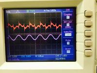
I'm working on an h-bridge and am experiencing issues with none other than the output voltage waveform. In short, it's just not AC. Looking at the current;however, is much more appealing as it is nearly perfectly AC. So my question is- where have I gone wrong? My guess is the coil that I'm using (as the load). Maybe the possible combination of series inductance and capacitance produces some kind of overmodulation at my switching frequency?
This output is being driven by 4 mosfet fired by 2 lm2726 drivers.
I think my image is attached (I hope). I'm posting this on an iPad so I will have to check when I get home.
Btw, this is a from the ground up design. All components have been selected an individually bought. This is not an item you could buy on digikey.
Thanks in advance for your help


