Continue to Site

Welcome to EDAboard.com

Welcome to our site! EDAboard.com is an international Electronics Discussion Forum focused on EDA software, circuits, schematics, books, theory, papers, asic, pld, 8051, DSP, Network, RF, Analog Design, PCB, Service Manuals... and a whole lot more! To participate you need to register. Registration is free. Click here to register now.

H-Bridge for dc motor problem

Status
Not open for further replies.

kbtan

Member level 2
Joined
Jul 8, 2011
Messages
45
Helped
0
Reputation
0
Reaction score
0
Trophy points
1,286
Activity points
1,583
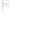
Hi, I am using a H-Bridge with 4 transistor(2 TIP31a, 2 TIP32a). Following is my circuit
H-bridge.jpg
I supply 12V to the collector of TIP31a and 3V to the base. Then motor will start run when I supply 3v to one side and other side to ground,but it run at about 2.3V instead of 12 V. How can I make the motor run at 12V???
 

Attachments

  • H-bridge.jpg
    H-bridge.jpg
    68.5 KB · Views: 101

Assume T1 and T4 are on.

What does the voltage at the left and right hand nodes of the motor need to be for these transistors to be on? Knowing this, what is the voltage across the motor?

My guess is that you got 2.3V from one terminal of the motor to ground, not across the terminals of the motor.
 
Last edited:

All your transistors are emitter followers so Vout = Vb -.7, i.e. 3 V minus a bit. To turn the motor on by 12 V, the bottom bas on one side needs, .7 V, the top transistor on the other side side needs greater then 12 V.
Frank
 

Check this site how to manage H-Bridge, which mislma that your scheme is wrong connection.

HTML:
http://www.hvlabs.com/hbridge.html

PS Sorry for my bad English.
 

Status
Not open for further replies.

Part and Inventory Search

Welcome to EDABoard.com

Sponsor

Back
Top