Continue to Site

Welcome to EDAboard.com

Welcome to our site! EDAboard.com is an international Electronics Discussion Forum focused on EDA software, circuits, schematics, books, theory, papers, asic, pld, 8051, DSP, Network, RF, Analog Design, PCB, Service Manuals... and a whole lot more! To participate you need to register. Registration is free. Click here to register now.

H bridge Design with p mosfet

Status
Not open for further replies.

rhnrgn

Member level 5
Member level 5
Joined
Dec 25, 2013
Messages
92
Helped
2
Reputation
4
Reaction score
2
Trophy points
1,288
Visit site
Activity points
2,069
I made the schematic i atteched, is there anything wrong? Because i couldnt find any problem but its not working at all :/

Yes i am noobie about p-mosfets =)

Mosfets,

irlu014npbf
**broken link removed**

17n80c3
http://www.infineon.com/dgdl/SPP_A1...8009b&fileId=db3a3043163797a60116385ea62e0101

zvp2110a
**broken link removed**


Schematic:
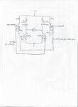
yazı1.jpg
 

Not sure what those source resistors are "47E". 47K? 47 ohm? Not sure why you need them at all. And are those 22K on the gates of the PMOSFETS? Why so high? The circuit looks basically correct, but I would verify several things:
1) Is it wired properly?
2) Is there enough gate drive to turn those mosfets on hard enough to handle the load? Nominally, they should see about 10V Vgs, you've only got 5V on the N-mos, and, I don't know WHAT the gate voltage on the P-MOS is (depending on what that 47E is). You'll note that everything for those FETS is speced at Vgs=10V.
3) You might want to look at using logic-level MOSFETS.
4) What's your load?
 
  • Like
Reactions: rhnrgn

    rhnrgn

    Points: 2
    Helpful Answer Positive Rating
What is the system doing?

Some notes:
When your N transistor drives the PMOS low it is just creating a voltage diver that ends up keeping the gate voltage on the PMOS at 8.17V. Depending on the PMOS this may keep it always off no matter how you switch it. You shouldn't need that 47K resistor anyways.
All the NMOS transistors don't have current limiting resistors for their gates. Depending on your 5V driving signal, it could damage the driving components from high current spikes.
I would add flyback diodes to mitigate the motor EMF.
Check the body diodes of the PMOS to make sure the orientation is correct in relation to the motor
 
  • Like
Reactions: rhnrgn

    rhnrgn

    Points: 2
    Helpful Answer Positive Rating
Not sure what those source resistors are "47E". 47K? 47 ohm? Not sure why you need them at all. And are those 22K on the gates of the PMOSFETS? Why so high? The circuit looks basically correct, but I would verify several things:
1) Is it wired properly?
2) Is there enough gate drive to turn those mosfets on hard enough to handle the load? Nominally, they should see about 10V Vgs, you've only got 5V on the N-mos, and, I don't know WHAT the gate voltage on the P-MOS is (depending on what that 47E is). You'll note that everything for those FETS is speced at Vgs=10V.
3) You might want to look at using logic-level MOSFETS.
4) What's your load?

1_i will check wires but i was not sure about design.
2_my load is 200ma 12v DC motor.
3_it is 47 K Ohm. Vgsth og p mosfet is min -2, max -4V. I was try to divide 12 volt and apply 8 volt (Vgs) gate of p mosfet in order to open it. Is this wrong idea?

- - - Updated - - -

What is the system doing?

Some notes:
When your N transistor drives the PMOS low it is just creating a voltage diver that ends up keeping the gate voltage on the PMOS at 8.17V. Depending on the PMOS this may keep it always off no matter how you switch it. You shouldn't need that 47K resistor anyways.
All the NMOS transistors don't have current limiting resistors for their gates. Depending on your 5V driving signal, it could damage the driving components from high current spikes.
I would add flyback diodes to mitigate the motor EMF.
Check the body diodes of the PMOS to make sure the orientation is correct in relation to the motor


System is driving a 12v 200ma DC motor in two directions by PIC MCU.

OMG you are right. -12V Vgs can open p mosfet too =) i thought it should be -4V Vgs thats why used voltage divider. :D

i will remove it and share results.
 

The emitter of the transistor that you have used to drive the P mos is connected to 47E resistance , try to reduce it to 10 ohms and add one more resistor to the collector of the transistor, the value of the two resistor(series) connected to the collector of BJT must be chosen in such a manner that on turning the bjt the voltage at the junction of two resistor should be greater than atleast 8 volts. you can connect 470 ohm resistance to collecter directly and connect 2.2k resistor between the other terminal of 470 ohm and 12 v supply .
this will solve your problem
 

Status
Not open for further replies.

Similar threads

Part and Inventory Search

Welcome to EDABoard.com

Sponsor

Back
Top