Continue to Site

Welcome to EDAboard.com

Welcome to our site! EDAboard.com is an international Electronics Discussion Forum focused on EDA software, circuits, schematics, books, theory, papers, asic, pld, 8051, DSP, Network, RF, Analog Design, PCB, Service Manuals... and a whole lot more! To participate you need to register. Registration is free. Click here to register now.

GSM SMS 8051 controlling relays

Status
Not open for further replies.
controlling relays with microcontrollers

Dear Yasir vai,
The AT_commands.pdf is not in active condition..rather the link is not working anymore..Byt the by thanks a lot for your informative...answer...
 
a1018s sms format

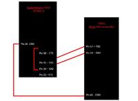
Hi. I'm using Multi-Tech's Socket Modem EDGE. i connected the TxD and RxD to the my 8051 Silab Microcontroller RxD and TxD respectively. But my GSM doesnt seem to response to my AT commands.
Should i tie the TxD of my modem to TxD of my MC and RxD to RxD?
I have also short CTS and RTS.

I have no idea what went wrong now...
:(
 

a1018s cmgf

@ dollar_124 : you are welcome! may be that pdf has been deleted by the moderators as i have come across this announcement after quite some time that all pdf documents would be deleted

@revenge :

?Generally while working with GSM modem,as far as i have experienced,you need to take into consideration following matters:

1. Need to take care of it whether you need to add some level shifter IC like maxc232 between modem signals and microcontroller if modem operates on R232 Link.
2. Normally one-to-one connection is made between (TxD,RxD,GND etc.) signals of modem and that of micrcontroller.

so these two matters can be established only if we consult the data sheet of your modem.

Tell me, what is complete part number of your modem for downloading its data sheet from internet.

till that time you try it by connecting TxD of modem with TxD of microcontroller and connect RxD of modem with RxD of microcontroller,GND obviously is common.
while shorten CTS of modem with its RTS.


regards
m.yasir
 

gsm module dhaka

my modem is MultiTech's Socket Modem EDGE - MTSMC-E. i'm going to try out connecting the TxD and RxD to the respective TxD and RxD...

Added after 20 minutes:

i've just changed the connections. it still doesnt work...
 

txd rxd rts cts telit microcontroller

can you please upload the circuit diagram through which you are trying to interface your modem with microcontroller.

Try one more thing,first interface it with your PC and send AT commands to it through HyperTerminal and see response of your modem

I try consulting its data sheet

regards
m.yasir
 

gsm modem receive code+8051

I'll already tried sending through HyperTerminal, it is normal (work-able).


Hopefully you can understand..
 

revenge sms pdf

You should be connecting the TX of the uP to the RX of the modem and the RX of the uP to the TX of the modem. If your Modem has an RS-232 interface then you'll have to put a RS-232 converter (i.e. MAX232) between the uP and the Modem.
 

sms read+avr

i was originally doing TxD to RxD.
but since it cant work too so i took yasir's suggestion of doing TxD to TxD.

Well,
I'm still trying to look for solutions..
 

sample c program of making relay on by gsm

revenge said:
I'll already tried sending through HyperTerminal, it is normal (work-able).
If you can send through a PC then simply duplicate the connections. However, YOU NEED TO ADD AN RS-232 CONVERTER (not shown in your schematic). Without it, you will NOT have the correct voltage levels or logic state require to communicate between the uP and the Modem.
 

c168i interface with uc

I have good practical experience working with simple GSM/GPRS modem (wismo quik 2403A) and with reference to my experience with simple GSM modem and based upon my experience with simple GSM/GPRS modem i can say that in case of simple GSM/GPRs modem you need to connect TxD of simple GSM/GPRS modem with TxD of microcontroller and RxD of modem with RxD of microcontroller.

The modem that you are using seems to be equipped with advance features of EDGE (which provides three times faster speed than ordinary GPRS modem),but after having a brief overview of that data sheet of your modem i think its connections with microcontroller should be same as that of simpple GPRS/GSM modem because it also supports AT commands like simple GPRS modem...

To practically establish this fact you need to try following steps:

1. check out the interface of your modem with computer.If it is connected with PC through serial port (RS-232 interface) then check out whether TxD of PC's serial port (PIN#3) connects with TxD of your modem and whether RxD of PC's serial port (PIN#2) connects with RxD of your modem this would make it clear how you need to connect the RxD and TxD pins of your microcontroller with your modem's TxD and RxD etc.

2. After establishing and verifying the connections between PC's serial Port's TxD and RxD pins with modem's TxD and RxD pins through step 1,you need to try sending AT commands to the modem through Hyper Terminal by shortening RTS of modem with CTS pin of modem,connecting GND of modem with GND of PC's serial Port,and making TxD and RxD connections between modem and PC according to step1.


I am sure these two steps would definitely help you resolve your issue if your modem is using RS-232 interface.

Try these two steps and let me know what your findings are meanwhile i explore the data sheet of your modem further

regards
m.yasir

Added after 22 minutes:

GSM Man said:
If you can send through a PC then simply duplicate the connections. However, YOU NEED TO ADD AN RS-232 CONVERTER (not shown in your schematic). Without it, you will NOT have the correct voltage levels or logic state require to communicate between the uP and the Modem.

GSM Man has given you some valuable hints, like:

- you need to duplicate the connections of your PC with modem for connecting microcontroller with your modem (in case if your modem connects directly with serial port of your PC through RS-232 port that i think does)

- Also if it connects with serial port of your PC directly through RS-232 link then you would definitely need Rs-232-to-TTL converter ICS like Max232 to interface your modem with microcontroller.I also find this voltage level shifter ICs in your diagram missing.

One more important thing that i would like you to take into consideration is that using only there connections of modem TxD,RxD and GND while RTS shortened with CTS of modem you cannot use GPRS or EDGE of modem.You can only send and receive SMS through these 3-pin connections.

regards
m.yasir
 
advisor motorola cable pinout

Thanks for the great info.
Regarding the use of GPRS and EDGE, currently i only need to send and receive SMS, so it doesnt matter.

I'll get down to try out all the possiblities and get back after I'm done. :)

Added after 9 minutes:

To add on, currently i'm working on the GSM module WITHOUT the development kit (DK). (Just the module itself).

I tried it on the DK through HyperTerminal and it's okay.
So i now need to take out just the GSM module and integrate with my uC.
After which i met all the problems mentioned above. :|
 

read sms from gsm modem in proteus

well,this development kit (DK) can help a lot in tracing the problem.

you simply need to trace connections of PC's TxD and RxD pins down to the corresponding connections of GSM/GPRS module, while your module is inserted in the DK.

Also note the connections of any voltage level shifter ICs (if there is any) betwen GPRS/GSM module and PC's port

regards
m.yasir
 

t290i data cable diagram

There's one problem, i can't seem to find the datasheet for my DK.

It's MultiTech MTSMI-UDK.
I search it and it shows the data sheet for the GSM module instead.
 

we have a project almost similar to these... because we want to extract incoming text messages receive by a phone to be transmitted to an 8051 microcontroller or Atmel AVR uC via bluetooth... how can we do it? i hope somebody can help us... many many thanks in advance...
 

please help me

i want to interface fingerprint detector with microcontroller 89c51 and then i want to interface it with GSM moderm

any body have the circuit diagrm.

pls mail me

my email id is

cool_vicky89@yahoo.com
 

ronydc said:
DEAR FRIENDS,

OK .. THR IS A LOT OF DISCUSSIONS ON SENDING THE SMS THROUGH MOBILE PHONE

LETS NOW TALK ABT RECEIVING sms AND MAKING A RELAY ON WITH 8051 CONTROLLER.


IF SOME ONE HAS DONE ANYTHING.. ABOUT THIS USING at commands,
please share it

---> reply and share only -----> 8051 with GSM modem
( not with mobile phone and fbus)

waiting for some expert to break the silence on this topic.
my findings till now are below.

--reciving sms in text mode are not performing the job. to make the realay on with sms.

-- may be forcefully need to apply the PDU mode.

please comment and show the way THIS can help a lot of forum members.

- Rony

Hello dear ronydc

am need that same project for my personal use plese send it me source code with circuit diagram its urgent
my id kesavanmdk@gmail.com

Added after 12 minutes:

Dear rony i need gsm contolling 8 relay project source code and circuit diagram send it kesavanmdk@gmail.com
 

Dear Yasir;

I have written the code for sending & recieving SMS with ATMEGA32 & wavecom modem in CODEVISION AVR compiler. My code does not work with Modem. Some times it work with PC Hyper terminal. Can you please find the problem?


Code:
Chip type               : ATmega16
Program type            : Application
AVR Core Clock frequency: 8.000000 MHz
Memory model            : Small
External RAM size       : 0
Data Stack size         : 256
*****************************************************/
#include <mega16.h>

// Standard Input/Output functions
#include <stdio.h>
#include <string.h>
#include <delay.h>

// Declare your global variables here

#define NO_OF_SEND_TRY 3

// Declare your global variables here
char data; // Use for data read purpose
char Msg_source[15];
char Msg_command[30];

int New_msg_flag =0;
int Handshake_status =0;
int Delete_status=0;

int No_of_send_msg1=0;
int No_of_send_msg2=0;
//int i;
//1. This function is used to read the available data
//from USART. This function will wait untill data is
//available.
char USARTReadChar()
{
   //Wait untill a data is available
   while(!(UCSRA & (1<<RXC)))
   {
      //Do nothing
   }
       //Now USART has got data from host and is available is buffer
   return UDR;
}
//This fuction writes the given "data" to the USART which then transmit it via TX line

void USARTWriteChar(char data)
{
   //Wait untill the transmitter is ready
  while(!(UCSRA & (1<<UDRE)))
   {
      //Do nothing
   }

   //Now write the data to USART buffer
   UDR=data;
}

int Handshake()
{
    int response1=0;
    int response2=0;
     /* Now send the AT command */    
    USARTWriteChar('A');
    USARTWriteChar('T');
    USARTWriteChar('\n');          
    //Check whether response is OK or not
     delay_ms(300);
    data=USARTReadChar();                
    if(data=='O')    
     {
      data=USARTReadChar();
      if(data=='K')        
              response1=1;
      else
              PORTA |=(1<<2);
     } 
    else
          PORTA |=(1<<1);
    USARTWriteChar('A');
    USARTWriteChar('T'); 
    USARTWriteChar('+');         
    USARTWriteChar('C');
    USARTWriteChar('M');
    USARTWriteChar('G');
    USARTWriteChar('F');
    USARTWriteChar('=');
    USARTWriteChar('1');
    USARTWriteChar('\n');
//Check whether response is OK or not
 delay_ms(300);
    data=USARTReadChar();                
    if(data=='O')        
     {
       data=USARTReadChar();
       if(data=='K')        
              response2=1;
    else
      PORTA |=(1<<4);
     }  
    else
       PORTA |=(1<<3);   
              
if (response1 && response2)    
    return 1;
else
    return 0;
}

void Create_send_msg(int index)
{
  char Output_msg [80];  
  char Ctrl_Z[3];
  int i=0;
                                
  Ctrl_Z[0]=(char)26;
  Ctrl_Z[1]='\0';
  
  strcpy (Output_msg,"AT+CMGS=\"01711136358\"\n");
  if (index == 7)
       strcat (Output_msg,"Port D bit 7 is ON");
  if (index == 6)                         
       strcat (Output_msg,"Port D bit 6 is ON");
      
  strcat (Output_msg,Ctrl_Z);
  while (Output_msg[i]!='\0')
  {
   USARTWriteChar(Output_msg[i]);
   i++; 
  }       
   delay_ms(100);
}

void Delete_msg()
{
    Delete_status=0;
    USARTWriteChar('A');
    USARTWriteChar('T'); 
    USARTWriteChar('+');         
    USARTWriteChar('C');
    USARTWriteChar('M');
    USARTWriteChar('G');
    USARTWriteChar('D');
    USARTWriteChar('=');
    USARTWriteChar('1');
    USARTWriteChar(',');
    USARTWriteChar('2'); 
    USARTWriteChar('\n');
  //Check whether response is OK or not
   delay_ms(100);
    data=USARTReadChar();                
    if(data=='O')        
      data=USARTReadChar(); 
    if(data=='K')
      {       
        Delete_status=1;
        PORTA |=(1<<5);
       //PORTA3=1;
        delay_ms(100);
       } 
}

void Process_msg()
{
 int i; 
  /*This function is called when it comes from authenticated source
and then it already read the send device no and so discard the next
25 charecter to find the original message */
  for(i=0;i<25;i++)  
     data=USARTReadChar();         
  i=0;   
  data=USARTReadChar();  
  //check for '.' as command ends with . Valid command can be 
  // bit 7 on. or bit 7 off. 
  while (data!='.')
  {
   Msg_command[i]=data;
   i++;                
   data=USARTReadChar();
  }
  Msg_command[i]='\0';
  if (strcmp(Msg_command, "bit 6 on")==0)
        PORTA |=(1<<6);                  
  //if (strcmp(Msg_command, "bit 5 on")==0)
    //    PORTB |=(1<<5);
  if (strcmp(Msg_command, "bit 6 off")==0)
        PORTA &=~(1<<6);                  
 // if (strcmp(Msg_command, "bit 5 off")==0)
   //     PORTB &=~(1<<5);       
  delay_ms(100);     
     
  Delete_msg();
   delay_ms(100);       
}        

void Read_msg()
{
 /* Now send the AT + CMGL =1 command; This will read the 1st SMS*/    
 int i;
    USARTWriteChar('A');
    USARTWriteChar('T'); 
    USARTWriteChar('+');         
    USARTWriteChar('C');
    USARTWriteChar('M');
    USARTWriteChar('G');
    USARTWriteChar('R');
    USARTWriteChar('=');
    USARTWriteChar('1');
    USARTWriteChar('\n');
                     
    delay_ms(100);
//Check whether response starts with '+' which indicate message arrives
    data=USARTReadChar();                
    if(data!='+')        
     {
      New_msg_flag=0;
     }  
     else
     {
        New_msg_flag=1; 
        PORTA |=(1<<7);
       //PORTA7=1;
        delay_ms(300);
        New_msg_flag=0;
        for(i=0;i<20;i++)  //discard the following 20 charecter to find the mobile no //
          data=USARTReadChar();
        for (i=0;i<14;i++) //collect the source device Identification Number //
        {
          data=USARTReadChar();
          Msg_source[i]=data;
        }
        Msg_source[i]='\0'; 
             
        if (!strcmp(Msg_source, "+8801711136358"))  
         {
          Process_msg();
          Delete_msg();
         }
        else
        {
         //From other source, so delete the message
         Delete_msg();
        } 
     
     }
}

// Declare your global variables here


void main(void)
{
// Declare your local variables here

// Input/Output Ports initialization
// Port A initialization
// Func7=Out Func6=Out Func5=Out Func4=Out Func3=Out Func2=Out Func1=Out Func0=Out 
// State7=0 State6=0 State5=0 State4=0 State3=0 State2=0 State1=0 State0=0 
PORTA=0x00;
DDRA=0xFF;

// Port B initialization
// Func7=In Func6=In Func5=In Func4=In Func3=In Func2=In Func1=In Func0=In 
// State7=T State6=T State5=T State4=T State3=T State2=T State1=T State0=T 
PORTB=0x00;
DDRB=0x00;

// Port C initialization
// Func7=In Func6=In Func5=In Func4=In Func3=In Func2=In Func1=In Func0=In 
// State7=T State6=T State5=T State4=T State3=T State2=T State1=T State0=T 
PORTC=0x00;
DDRC=0x00;

// Port D initialization
// Func7=In Func6=In Func5=In Func4=In Func3=In Func2=In Func1=In Func0=In 
// State7=T State6=T State5=T State4=T State3=T State2=T State1=T State0=T 
PORTD=0x00;
DDRD=0x00;

// Timer/Counter 0 initialization
// Clock source: System Clock
// Clock value: Timer 0 Stopped
// Mode: Normal top=FFh
// OC0 output: Disconnected
TCCR0=0x00;
TCNT0=0x00;
OCR0=0x00;

// Timer/Counter 1 initialization
// Clock source: System Clock
// Clock value: Timer1 Stopped
// Mode: Normal top=FFFFh
// OC1A output: Discon.
// OC1B output: Discon.
// Noise Canceler: Off
// Input Capture on Falling Edge
// Timer1 Overflow Interrupt: Off
// Input Capture Interrupt: Off
// Compare A Match Interrupt: Off
// Compare B Match Interrupt: Off
TCCR1A=0x00;
TCCR1B=0x00;
TCNT1H=0x00;
TCNT1L=0x00;
ICR1H=0x00;
ICR1L=0x00;
OCR1AH=0x00;
OCR1AL=0x00;
OCR1BH=0x00;
OCR1BL=0x00;

// Timer/Counter 2 initialization
// Clock source: System Clock
// Clock value: Timer2 Stopped
// Mode: Normal top=FFh
// OC2 output: Disconnected
ASSR=0x00;
TCCR2=0x00;
TCNT2=0x00;
OCR2=0x00;

// External Interrupt(s) initialization
// INT0: Off
// INT1: Off
// INT2: Off
MCUCR=0x00;
MCUCSR=0x00;

// Timer(s)/Counter(s) Interrupt(s) initialization
TIMSK=0x00;

// USART initialization
// Communication Parameters: 8 Data, 1 Stop, No Parity
// USART Receiver: On
// USART Transmitter: On
// USART Mode: Asynchronous
// USART Baud Rate: 9600
UCSRA=0x00;
UCSRB=0x18;
UCSRC=0x86;
UBRRH=0x00;
UBRRL=0x33;

// Analog Comparator initialization
// Analog Comparator: Off
// Analog Comparator Input Capture by Timer/Counter 1: Off
ACSR=0x80;
SFIOR=0x00;

while (1)
      {
      // Place your code here
      //Check whether AT command performs correctly or not 
      //return positive if success
      Handshake_status=Handshake();
      if(Handshake_status==0)
       {
       PORTA |=(1<<0);
       //PORTA0=1;
       } 
       //Led will go high to indicate red as handshake failed 

      
         Read_msg();
      
       //if (PORTD7==1 || PORTD6==1)
      if ((PIND & (1<<PIND7))&&(No_of_send_msg1<NO_OF_SEND_TRY))
         {
           Create_send_msg(7);
           delay_ms(300);    
           No_of_send_msg1++;
         }    
          
      if(No_of_send_msg1==NO_OF_SEND_TRY)
            {
             //PORTD &=~(1<<7);
             No_of_send_msg1=0;
             Delete_msg();
            }
         
     if ((PIND & (1<<PIND6))&&(No_of_send_msg2<NO_OF_SEND_TRY))
          {
           Create_send_msg(6);  
           No_of_send_msg2++;
           }    
       
    if(No_of_send_msg2==NO_OF_SEND_TRY)
            {
             //PORTD &=~(1<<6);  
             No_of_send_msg2=0;
             Delete_msg();
             }          
       }

}
 

sorry friends for being absant here for long time.. i was not well and could not be here on internet even.

so.. in this subject .. good discussions are going on i am seaing that.
I will shortly put my code and circuit here to end all this as the happy ending...!!

SOME points till then to remember.
1> reciving sms and make an led on.. is more difficult then sending the sms. when an instance occurs.
2>alwys use the text format for reciving. PDU is unnecessarily complicated.
3> after reciving sms, bypass the specific number of count to bypass the unnecessary string of letters got with sms and extract the message.
4> get that string in a saperate bufffer and compair with a pre defined string.
5> form now it becomes easy. -- just make an led on if the incoming string gets matched with the inside string -- "ledon"
6> enjoy... and send me many thanks..!!

this sequence will work with any micro controller in the World. and this is to be used with GSM modem.
by the way i did this even with the simple 89c51 microcontroller and got 100% success.

thx of all of you for Reading me.. i hope your things will work too. with my this Advise


your dear friend
-- Rony.
 

hey anybody plzz help me regarding sms based device controlling... i wana know how to interface physical port with virtual port....... i will be very thankful to you
 

Status
Not open for further replies.

Part and Inventory Search

Welcome to EDABoard.com

Sponsor

Back
Top