Continue to Site

Welcome to EDAboard.com

Welcome to our site! EDAboard.com is an international Electronics Discussion Forum focused on EDA software, circuits, schematics, books, theory, papers, asic, pld, 8051, DSP, Network, RF, Analog Design, PCB, Service Manuals... and a whole lot more! To participate you need to register. Registration is free. Click here to register now.

Ground current error in potential divider?

Status
Not open for further replies.

rswarbrick

Newbie level 4
Joined
Aug 22, 2012
Messages
5
Helped
0
Reputation
0
Reaction score
0
Trophy points
1,281
Activity points
1,340
Hi,

I've got a sort of repair / mod project going with an old Weir 430 power supply. I want to replace the (broken) analogue meter with a pair of 4 digit displays. The power supply is specified at 0-30V, 0-3A so I decided to use a 12-bit dual ADC with a 4.096V reference (4096 count, so 1mA resolution). Getting 12 bit precision over (say) a 20°C range seems non-trivial in various ways, but I had one specific question:

The connections I'm going to have to my board have the following voltages (in increasing order)
  1. Case Ground (0V)
  2. Output Voltage (0-30V)
  3. Above current shunt (0-30.75V)
  4. Internal supply rail (6.8 - 36.8V)

My plan was to use a 9:1 potential divider to make a new ground reference at 90% of the output voltage. In order not to fry the ADC or some other digital parts, I would use a 5V regulator from the supply rail. Then there would be a precision InAmp to measure from the current shunt and some passives etc. The two voltages measured by the ADC would then be the output voltage rail (now 0-3V) and the difference from the InAmp, amplified with a gain of 4 to give it the same range.

Problem is, that presumably current going to ground will cause a greater voltage drop across part of the potential divider, messing up the voltage measurement. Am I right in expecting this and (more importantly!) how do people usually get around this?

Also, I presume that to get anywhere near the required precision, I'll need to use some sort of array for this divider. I'd guess I should use a part like this one from Susumu (link to Digikey product page). Is this the right idea?

Many thanks,

Rupert
 

Not quite sure what you mean by a "new ground reference". Don't you just mean you are dividing your input voltage with a divider to get 0-30-->0-3? If that's the case, and your opamp has high-enough input impedance (which it should), this should work just fine. Also, that array might be overkill. You can buy discrete resistors with 0.1% (or better) tolerance. But if they've got that array in stock, go for it.
 

Not sure what you are saying about a "new ground reference". The ground stays the same. The resistor network you referenced should give an accurate 10:1 attenuation with the 1kΩ connected to ground and the 9kΩ connected to the output.
 

if you are worried that the current is so high that it would cause voltage drop in the wiring connected to the ground node, well don't worry about it. however as a safety precaution you can use large resistors in the divider to decrease its current.
for the precision part, you can also use a variable resistor and set it as you wish.
 

Ok, I wasn't clear. What I mean by a "new ground reference" is that all of my circuit will treat the intermediate voltage as ground. Of course, this means that the ADC, microcontroller, OpAmps, InAmp etc. will all draw current from the supply rail which then will return through my "new ground". This is connected to the actual case ground through the (say) 9kΩ resistor. As such, if my entire circuit is drawing a current of 1mA, there will be a voltage drop across this resistor of 9V(!!).

I think I probably want to buffer this with some sort of OpAmp circuit, but I'm not sure how is best. Moreover, this seems rather complicated and I was wondering if I'm just doing something weird. Maybe there's a standard way to solve this problem?

- - - Updated - - -

Don't you just mean you are dividing your input voltage with a divider to get 0-30-->0-3?

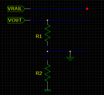
Ah, no. I mean I'm dividing with something like the image below, with R1/R2 = 9. Then the voltage difference between FAKEGND and V+ will be 0-3V. The problem is that all return currents now go through FAKEGND, leading to a voltage drop across R2.

out.png

(There is also a current shunt input, 0-0.75V above VOUT)
 
Last edited:

Why are you trying to move the ground point? :?: You measure the attenuated voltage between the resistor junction and the original ground (1k ohm to ground).
 

Terrible idea. No, REALLY terrible idea. Ground needs to be a low impedance point, you're making it 9K. There is no reason to do this. Divide your voltage, keep your original ground and be done with it.
 

Ok, fair enough. So presumably I should use a linear regulator or buck converter or something to bring down the supply rail to something closer to case ground if necessary (in order not to fry the ADC etc.)

There's still the problem of the current shunt. I don't think instrumentation amplifiers are usually happy with subtracting things at ~30V. Should I divide down those two voltages too? Of course, then I need to amplify the difference back up with a higher gain (presumably 40). I guess I could divide both sides of the current shunt by a different amount too - am I going to get the most accurate result by dividing by 10 and then multiplying again, or is there an intermediate value I should expect to be more accurate?

I'm also little cautious about the fact I'll need two potential dividers, one to divide the Vout and one to divide "Vshunt". Re trimming pots: Is there a cleverer trimming strategy than "get it right at 0 current, then sort out the shunt" ?
 

You could use a current shunt monitor such as one of these.

You may have to add a trim pot if you need current accuracy higher than the intrinsic accuracy of the circuit. But usually high accuracy is not needed for current measurements.
 

You may have to add a trim pot if you need current accuracy higher than the intrinsic accuracy of the circuit. But usually high accuracy is not needed for current measurements.

Right, sorry I thought I explained that I wanted 1mA resolution over 0-3A. Since that's 3000 count, it's 12-bit resolution, which is rather higher accuracy than dedicated current shunt monitors tend to be.
 

Right, sorry I thought I explained that I wanted 1mA resolution over 0-3A. Since that's 3000 count, it's 12-bit resolution, which is rather higher accuracy than dedicated current shunt monitors tend to be.
I forgot. :oops: Yes, you did state that you needed 1mA resolution. Do you also need an absolute accuracy of 1mA?

For that accuracy you will likely have to calibrate the current sense circuit for both offset (zero current output) and gain (full scale output) which could be done with a couple of properly placed trimpots in the circuit.
 

Status
Not open for further replies.

Similar threads

Part and Inventory Search

Welcome to EDABoard.com

Sponsor

Back
Top