ekrzychoooo
Newbie level 2

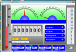
I would like to present my project salamander.
The main idea of ??the salamander to enable easy configuration panel communicates with the microcontroller.
This can be a fun alternative to the terminal if you want to show on your PC screen data from our ADC uC eg, temperature, logic states.
The program also allows you to set / reset bits in the ports by clicking the mouse in the right bottom or set of analog values.
The entire panel composes of different elements that can be added as needed.
Each of the elements can be placed on the panel at any point by dragging it with the mouse.
Each element has a number of settings related to the appearance such as width, height, display range values.
Each element has its own address.
The program is free and available for download at **broken link removed**
Configure the following panel as below takes a few minutes.

Installation
After downloading the software installs in a standard way through the installer ..
It is recommended that before you uninstall the previous installation.
The default is installed in "c: \ program files \ Salamander".
Setup creates the "my documents" folder salamander, which is used to store configuration data.
Proper operation requires the installation of Java JRE 1.7
Configuration.
On the "Tools" menu, select "Settings". This opens a blank panel
Now, with the list of items to select what interests us and click 'add'.
Use the mouse to drag the item to our panel. In the left pane displays the configuration module added item.
Characteristic elements
Thermometer
Element shows the data in the form of a thermometer bar. In this element can set a minimum and maximum value.
This is the range of the measured values.
Example frame setter value of 21.5 in the element with the address 22 (decimal).
LF_0__0_1__6_4__2_1__._ 5_CR
0A 30 30 31 36 34 32 31 2E 35 0D

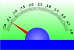
analog Meter
Element simulating analog meter. The element can set the range of the measured values ??and the size.
Example frame setter value of 15.3 in the element with the address 1234 (hex).
LF 1 2 3 4 4 1 5. 3 CR
0A 31 32 33 34 34 31 35 2E 33 0D

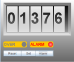
counter
The element can count events. You can set the number of digits and the size of graphic element.
Counter allows you to increase the value other than one. Information increasing step is included in a data frame. While the program is the ability to set the initial value of the counter, alarm values ??and reset to zero.
Counter after reaching an alarm is signaled by the sound.
Example frame counter increasing by 5 at address 3 (dec);
LF 0 0 0 3 1 5 CR
0A 30 30 30 33 31 35 0D

element LED
Element is used to provide binary signals. You can configure the number of binary states in the range of 1 to 8, and the width and height of the element.
Height set by adjusting the font size of labels describing the signals. States led correspond to the bits in the data word. To light up all the LEDs should be sent to the value of FF and to suppress the value of 00
Frame sets the first 4 leds in the element with the address 32 (decimal)
LF 0 0 2 0 2 0 F CR
0A 30 30 32 30 32 30 46 0D
Text Label.
A text element is used to describe. These elements are in a layer over all the elements so they can be arranged in the area of other elements.
It is possible to set width, height, font size, color, and transparency.
This element can also be set by the incoming frame.
Example frame setter to "Volt" in the element of the address 0x0001.
LF 0 0 0 1 4 V o l t CR
0A 30 30 30 31 34 56 6F 6C 74 0D
Element switches.
Element is used to change the binary states. You can set the height, width and number of keys in the range 1 to 8
The data represent a byte whose bits correspond to an individual bits.
Example frames generated by setting all keys ON
LF 0 0 2 0 2 F F CR
0A 30 30 32 30 32 46 46 0D
Slider element
Element is used to set the analog values. You can set the width, height, and the range of the setting values??.
During operation, a new value can be set using the slider or by entering a value in the text box and approving the "Enter" key.
Frame created after setting the 68 (dec) with address 5
LF 0 0 0 5 2 4 4 CR
0A 30 30 30 35 32 34 34 0D
Video tutorial:
sample program for atmega8:
View attachment adctosalamandra.zip
The main idea of ??the salamander to enable easy configuration panel communicates with the microcontroller.
This can be a fun alternative to the terminal if you want to show on your PC screen data from our ADC uC eg, temperature, logic states.
The program also allows you to set / reset bits in the ports by clicking the mouse in the right bottom or set of analog values.
The entire panel composes of different elements that can be added as needed.
Each of the elements can be placed on the panel at any point by dragging it with the mouse.
Each element has a number of settings related to the appearance such as width, height, display range values.
Each element has its own address.
The program is free and available for download at **broken link removed**
Configure the following panel as below takes a few minutes.

Installation
After downloading the software installs in a standard way through the installer ..
It is recommended that before you uninstall the previous installation.
The default is installed in "c: \ program files \ Salamander".
Setup creates the "my documents" folder salamander, which is used to store configuration data.
Proper operation requires the installation of Java JRE 1.7
Configuration.
On the "Tools" menu, select "Settings". This opens a blank panel
Now, with the list of items to select what interests us and click 'add'.
Use the mouse to drag the item to our panel. In the left pane displays the configuration module added item.
Characteristic elements
Thermometer
Element shows the data in the form of a thermometer bar. In this element can set a minimum and maximum value.
This is the range of the measured values.
Example frame setter value of 21.5 in the element with the address 22 (decimal).
LF_0__0_1__6_4__2_1__._ 5_CR
0A 30 30 31 36 34 32 31 2E 35 0D
analog Meter
Element simulating analog meter. The element can set the range of the measured values ??and the size.
Example frame setter value of 15.3 in the element with the address 1234 (hex).
LF 1 2 3 4 4 1 5. 3 CR
0A 31 32 33 34 34 31 35 2E 33 0D

counter
The element can count events. You can set the number of digits and the size of graphic element.
Counter allows you to increase the value other than one. Information increasing step is included in a data frame. While the program is the ability to set the initial value of the counter, alarm values ??and reset to zero.
Counter after reaching an alarm is signaled by the sound.
Example frame counter increasing by 5 at address 3 (dec);
LF 0 0 0 3 1 5 CR
0A 30 30 30 33 31 35 0D

element LED
Element is used to provide binary signals. You can configure the number of binary states in the range of 1 to 8, and the width and height of the element.
Height set by adjusting the font size of labels describing the signals. States led correspond to the bits in the data word. To light up all the LEDs should be sent to the value of FF and to suppress the value of 00
Frame sets the first 4 leds in the element with the address 32 (decimal)
LF 0 0 2 0 2 0 F CR
0A 30 30 32 30 32 30 46 0D
Text Label.
A text element is used to describe. These elements are in a layer over all the elements so they can be arranged in the area of other elements.
It is possible to set width, height, font size, color, and transparency.
This element can also be set by the incoming frame.
Example frame setter to "Volt" in the element of the address 0x0001.
LF 0 0 0 1 4 V o l t CR
0A 30 30 30 31 34 56 6F 6C 74 0D
Element switches.
Element is used to change the binary states. You can set the height, width and number of keys in the range 1 to 8
The data represent a byte whose bits correspond to an individual bits.
Example frames generated by setting all keys ON
LF 0 0 2 0 2 F F CR
0A 30 30 32 30 32 46 46 0D
Slider element
Element is used to set the analog values. You can set the width, height, and the range of the setting values??.
During operation, a new value can be set using the slider or by entering a value in the text box and approving the "Enter" key.
Frame created after setting the 68 (dec) with address 5
LF 0 0 0 5 2 4 4 CR
0A 30 30 30 35 32 34 34 0D
Video tutorial:
sample program for atmega8:
View attachment adctosalamandra.zip
