Continue to Site

Welcome to EDAboard.com

Welcome to our site! EDAboard.com is an international Electronics Discussion Forum focused on EDA software, circuits, schematics, books, theory, papers, asic, pld, 8051, DSP, Network, RF, Analog Design, PCB, Service Manuals... and a whole lot more! To participate you need to register. Registration is free. Click here to register now.

[SOLVED] GPIO to max232 interfacing

Status
Not open for further replies.

Aya2002

Advanced Member level 4
Joined
Dec 12, 2006
Messages
1,140
Helped
184
Reputation
376
Reaction score
117
Trophy points
1,343
Location
Iraq
Activity points
8,006
Hello Friends,

I am currently connected my DE1 board (altera) using the GPIO_0[0] as Tx and GPIO_0[1] as Rx to MAX232N then to my PC, but I can not see any results neither in the DE1 board nor my PC,
I used the following schematic diagram but the capacitors were 0.1 µF

rs232schematic.png

Would you please help me.

Thank you
 

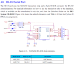
Your board manual shown the following connections for the on board MAX232

DE1_232.GIF

Are you trying to use an external MAX232 device?

Normally I would expect to see a MAX3232 which is specified to work with 3.3v but Altera has used instead a MAX232 with a 3.3v supply that is outside of the recommended supply range (4.5v-5.5v).
What is the supply voltage you have used? (assuming external device).

Alex
 
  • Like
Reactions: Aya2002

    Aya2002

    Points: 2
    Helpful Answer Positive Rating
yes, am using an external MAX232N device.

I used as a supply voltage the vcc provided by the GPIO (pin number 11).

before I use pin 11, I used an external supply but i faced the same problem.
 

If I'm reading the manual correctly then you have used a 5v supply and although there is no problem for the pin that goes from the FPGA to max232 I think there is a problem with the pin that comes from MAX232 to the FPGA which will have 5v and your FPGA is not 5v tolerant I think although there are resistors that probably protect the pin.

I'm not sure if this is the problem but try to supply the chip with 3v3 as with the on board 232 or even better use a MAX3232.

The user manual shows 3v3 supply to pin 29 of GPIO
 
  • Like
Reactions: Aya2002 and FvM

    FvM

    Points: 2
    Helpful Answer Positive Rating

    Aya2002

    Points: 2
    Helpful Answer Positive Rating
The DE1 on-board MAX232 is operated with VCC of 3.3V to keep the rated Cyclone II input voltage range for the RX line. When you connect a standard 5V operated MAX232 or any other digital signal with 5V output, the logic levels towards FPGA should be divided or clamped to about 3.3V. The best way is to use a 3.3V compatible MAX232, as for the on-board interface.

Not observing the input voltage rating can cause damage of FPGA IO buffers, at least on long term. The point doesn't explain the problems you observe.

I see, Alex has just explained the same facts.
 
  • Like
Reactions: Aya2002

    Aya2002

    Points: 2
    Helpful Answer Positive Rating
Also the MAX232 datasheet shows 1uf capacitors, I'm not sure why you have used 0.1uf
 

Do you think that 3232 will perform better? is its output to TTL/CMOS will be 3.3 volt?
 

Do you think that 3232 will perform better? is its output to TTL/CMOS will be 3.3 volt?
Yes, when supplied with 3.3V.
 
  • Like
Reactions: Aya2002

    Aya2002

    Points: 2
    Helpful Answer Positive Rating
Also the MAX232 datasheet shows 1uf capacitors, I'm not sure why you have used 0.1uf

because max232n needs 0.1

- - - Updated - - -

Yes, when supplied with 3.3V.

Ok, thanks, I will buy tomorrow on MAX3232 and try again and sure I will update my results here.

Thank you again
 

Ok, I will try now to change it to 1 uF and see.
 

If the capacitors are suffcient or not, and if the MAX232 voltage generator is working at all, will show by measuiring the voltage at the V+ and V- pins. Did you ever check?
 
Ok, I will try now to change it to 1 uF and see.

i faced the same problem, I think it is better to try the MAX3232. I will buy tomorrow one MAX3232 and try again

thank you for your help

- - - Updated - - -

If the capacitors are suffcient or not, and if the MAX232 voltage generator is working at all, will show by measuiring the voltage at the V+ and V- pins. Did you ever check?

pin 2 = 7.5 volt
pin 6 = -7.5 volt

Note the supply now is 3v3 and the capacitors are 1 uF

but the same problem is appeared !!!
 

Have you tried a loop back?
Disconnect the RX, Tx from the FPGA and connect them one to the other (the TTL pins), then try to sens one character from the PC and see if it gets printed back.
This would ensure that the PC console, wire and MAX232 are fine.
 

Hello my colleagues, Now I connected the MAX3232. The supply voltage is 3v3 (pin 29).

I did not see my expected results!!!
 

Is the loopback test OK?

What exactly is the problem you are facing (no char at all, unrecognized characters etc), can it be related to the FPGA code?
If you use the same code with the onboard MAX232 does it work ok?

Did you try with lower baud rates?
 

Is the loopback test OK?

What exactly is the problem you are facing (no char at all, unrecognized characters etc), can it be related to the FPGA code?
If you use the same code with the onboard MAX232 does it work ok?

Did you try with lower baud rates?

as soon as I send any char from the pc to the FPGA, I receive 11111111 (or FF). I can not detect any thing on my pc from the FPGA when i try to send.

However, I used the VHDL code with the onboard rs232 and everything is fine.

- - - Updated - - -

I do double check for all the connections and all are correct

- - - Updated - - -

Just now I did the loopback test (from the FPGA to FPGA). The test was successfully transmit and receive without errors !!!! this means the problem is outside the FPGA board.

- - - Updated - - -

I will try to use an external supply. I already buy a regulator LM1117T and check again
 

My personal favorite is always baud rate mismatches. Check check and double check the baud rate. And as already suggested, try it with lower baud rates.
 

as soon as I send any char from the pc to the FPGA, I receive 11111111
In other words, you receive a start bit? A way to check the RS232 interface and FPGA UART design wouldbe to watch the RX and TX signals with an oscilloscope. The received RX line and internal UART signals can be monitored with SignalTap.
 
  • Like
Reactions: Aya2002

    Aya2002

    Points: 2
    Helpful Answer Positive Rating
Status
Not open for further replies.

Part and Inventory Search

Welcome to EDABoard.com

Sponsor

Back
Top