Ng Jing Xi
Newbie level 1

- Joined
- Oct 18, 2013
- Messages
- 1
- Helped
- 0
- Reputation
- 0
- Reaction score
- 0
- Trophy points
- 1
- Activity points
- 9
Hi,
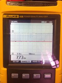
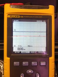
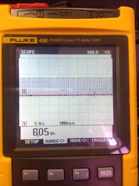
So I was able to generate a PWM signal. However, when I pass it through the IR2113, the Ho only shows a constant DC line while the Lo shows the PWM signal. Anyone has any idea on why the high side is unable to work?
The waveform shown below are taken before connecting to the IGBT, [After R9, R10]
The red line indicates the 0V reference line
I had attached my schematic design for reference as well.


