SK245230
Member level 3
Hi Edaboard community, I have a quick question about rectifiers.
It seems that when you run an AC simulation with a rectifier, the rectifier behaves like if there is nothing.
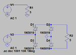
Below I show what i'm talking about. I simulate an AC source with a 5 ohm resistor (R1) and same resistor (R2) with a rectifier.

The current that goes in R1 is 200mA and the current that goes in R2 is 0. This is logic because there is no AC current that goes through R2, it is DC current.
But I have some troubles here with the AC source. In time based world, the source gives AC power to the rectified load, but when you run AC simulation with rectifier, the source gives nothing. This is disturbing for me.
AC simulation:
I(V2)= 0mA (AC)
Transient simulation:
I(V2)= 60mA (AC)
However, one question arrise. how can you run AC simulation with rectifiers so that the source behaves like it should. Is there maybe a kind of equivalent circuit or model for the rectifier?
How do you run AC simulation with rectifiers?
I'm asking this because I am working with AC to DC applications and I can't find a way to have a rectified load that behaves correctly in AC simulation.
It seems that when you run an AC simulation with a rectifier, the rectifier behaves like if there is nothing.
Below I show what i'm talking about. I simulate an AC source with a 5 ohm resistor (R1) and same resistor (R2) with a rectifier.

The current that goes in R1 is 200mA and the current that goes in R2 is 0. This is logic because there is no AC current that goes through R2, it is DC current.
But I have some troubles here with the AC source. In time based world, the source gives AC power to the rectified load, but when you run AC simulation with rectifier, the source gives nothing. This is disturbing for me.
AC simulation:
I(V2)= 0mA (AC)
Transient simulation:
I(V2)= 60mA (AC)
However, one question arrise. how can you run AC simulation with rectifiers so that the source behaves like it should. Is there maybe a kind of equivalent circuit or model for the rectifier?
How do you run AC simulation with rectifiers?
I'm asking this because I am working with AC to DC applications and I can't find a way to have a rectified load that behaves correctly in AC simulation.