fethiyeli
Full Member level 4

- Joined
- Feb 9, 2013
- Messages
- 207
- Helped
- 10
- Reputation
- 20
- Reaction score
- 12
- Trophy points
- 1,298
- Activity points
- 2,986
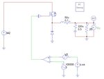
Hi everyone, i got a bode plot of a buck converter. Actually, my own circuit is full bridge but its written in textbooks that full bridge is buck derived converter. So i thought i can use the buck circuit below i have taken from basso's textbook. I only changed frequency because in buck converter, switching frequency equals to output ripple frequency but in full bridge, output ripple is double of the switching frequency. In my full bridge circuit, switching frequency was 50kHz. Thats why i changed it into 100kHz in order to get 100kHz output ripple frequency. I got bode plot and phase margin for buck converter but i dont know whether i can use it for half bridge or full bridge or any kind of buck derived converter. For now, i need bode plot for full bridge. If the answer is yes, then i can use the basso's equations directly. I opened different topic because i didnt use any kind of IC. I have also seen that basso had used that buck circuit for AC analysis.
Vin max = 342VDC
Vo = 70V
fsw = 50 kHz
Iout min = 1.4A
Iout max = 14.29A
Po = 1000W
Vin max = 342VDC
Vo = 70V
fsw = 50 kHz
Iout min = 1.4A
Iout max = 14.29A
Po = 1000W

