Continue to Site

Welcome to EDAboard.com

Welcome to our site! EDAboard.com is an international Electronics Discussion Forum focused on EDA software, circuits, schematics, books, theory, papers, asic, pld, 8051, DSP, Network, RF, Analog Design, PCB, Service Manuals... and a whole lot more! To participate you need to register. Registration is free. Click here to register now.

Full bridge CCFL inverter simulation and testing.

Status
Not open for further replies.

kudjung

Member level 4
Joined
Jan 17, 2003
Messages
77
Helped
2
Reputation
4
Reaction score
2
Trophy points
1,288
Activity points
734
Guys,

I've tried to study full bridge inverter for driving the CCFL lamp with a development actual board that I have. Actual board work as expected but the simulation doesn't seem to coorelate well with the actual board.

Here are some of the detail.

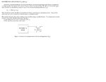
On actual board, There's a single chip CCFL full bridge controller driving 4 Mosfet. The Mosfet then drive the transformer with following manufacturer spec.

Primary Inductance = 210 uH.
Primary leakage inductance = 40 uH.
Secondary Inductance = 1.44H.
Secondary leakage inductance = 290mH.
Turn Ratio(1:82.6)


On the simulation, I drive 4 Mosfet with duty cycle and period close to what I've measured on the actual board.

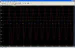
On the actual board I got close to 600 Vrms across 00KOhm load but with the simulation I only get close to 300 V(p-p).

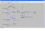
I've attached here the simulation schematic and test result. Also I attached my LTspice simulation file.
Just wondering whether anyone can point out whether I might do anything wrong with this simulation.

Thanks,
KJ
 

Attachments

  • ccfl_fullbridgedirve_delta_trans_1.zip
    1.4 KB · Views: 132
  • Transformer for CCFL inverter module.JPG
    Transformer for CCFL inverter module.JPG
    261.4 KB · Views: 186
  • CCFL_DRIVE_SIMULATION.JPG
    CCFL_DRIVE_SIMULATION.JPG
    195.6 KB · Views: 203
  • ccfl_drive_result.JPG
    ccfl_drive_result.JPG
    161.6 KB · Views: 168

Hello,

You may remove the leakage inductance at the secundary site. The 40 uH primary leakage inductance also includes the secundary leakage inductance (you may prove this yourself in simulation). Take the transformer out of the circuit, short circuit the primary and "measure" the secundary inductance via simulation.

based on the secundary inductance values, the coupling factor would be around 0.89. So 1V input would give about 0.89*82.6V at the output. When I look to your transformer model, 1V in would result in 0.8*82.6V (based on 170/(40+170). Maybe you have to change your turns ratio in the ideal transformer (from 82.6 to 82.6/0.89)
 
Last edited:
  • Like
Reactions: kudjung

    kudjung

    Points: 2
    Helpful Answer Positive Rating
Hi WimRFP,

Thanks a lot for your help. Problem is the leakage inductance on the primary side as you pointed out.
One more thing that I still not completely understand. I need to remove the exciting inductance to get correct valu of secondary leakage inductance in simulation. Is this the correct way to do for secondary leakage inductance.

Thanks,
KJ
 

In addition, your transformer model is missing the windings capacitance.

P.S.:
I need to remove the exciting inductance to get correct valu of secondary leakage inductance in simulation.
You don't remove it. Primary and secondary leakage inductance are the same thing, just tranformed by the (n1:n2)².

It's the same with main inductance. Instead of using an ideal transformer, you would normally place primary and secondary inductance, linked by a coupling factor of 1.
 
Last edited:

Normally I model transformers as FvM described, just inductors and a coupling factor ("K" in my spice version).

If you remove the secondary leakage inductance and short the secondary, your 170 uh will be shorted by the ideal transformer. So this should result in your 40uH leakage inductance.

If you leave the secondary open, you will measure 40uH + 170uH and that is the primary inductance (the datasheet mentions wrong value in my opinion).

Did you simulate the transformer separately (or even measured it sepatately)?

As FvM said, your model doesn't include capacitances. you may measure the self resonant frequency of the transformer (or just measure impedance versus frequency) to make a guess on the capacitances.
 

Thanks WinRFP/FVM,

I've simulated the transformer seperatly. Now, I re-do the simulation again usnig coupled inductor and the value is close to the datasheet.

I'm interested about the winding capacitance measurement and simulation.
I found this method attached. Is this the method that you refered to.

-I don't have Q meter or impedance meter. I do have a low cost function generator and oscilloscope. Can I use this to find resonant frequency by vary frequency and see its peak. My function generator probably don't have enough driving current so maybe I just serie with some resistor. Do you think this will be ok to check resonant frequency?

-I'm not sure I understand this test method(attached) correctly. For "Cd" value from this measurement method(as attached), will it include both primary and secondary capacitance? If so, I just put Cd value across Lm in my previous transformer model,correct?

Thanks,
KJ
 

Attachments

  • Measuring_Cp_and Cs.JPG
    Measuring_Cp_and Cs.JPG
    59.9 KB · Views: 131

In a step-up transformer, you can expect most of the effective windings capacitance localized in the secondary winding. This should be reflected in your model.

To measure individual windings capacitances, you would need to short windings and rely on resonances with leak inductences. An accurate measurement of the primary capacitance may be difficult without disassembing the transformer.
 

Good to hear that simulation comes closer to measurement.

You have a transformer where the secondary has a sectional structure, so the capacitance will not be very high. In addition, the impedance at the operating frequency is very high (400 kOhms inductive impedance). Capacitance will be in the low pF region and therefore difficult to measure as your oscilloscope probe has more capacitance. .

You may drive the secondary from your function generator via a small capacitor in series (say 1 pF) and using highest voltage drive. Leave the primary unconnected. When you just keep the oscilloscope probe close to the hot site of the secondary, you may see a resonance peak during a manual frequency sweep. The coupling through the probe is via the transformer to probe tip capacitance. Don't forget the ground the probe at the "cold" side of the transformer (this is the pin where you also connect the ground from the function generator).

You can calculate the capacitance and subtract the value of the series capacitor. If the value found is far below the value of the series capacitor, reduce the series capacitor and do the measurement again. Hopefully the Q of the transformer is sufficiently high that you can notice a peak.

The measured value, you just put across the secondary output of the transformer.
 

Status
Not open for further replies.

Part and Inventory Search

Welcome to EDABoard.com

Sponsor

Back
Top