Continue to Site

Welcome to EDAboard.com

Welcome to our site! EDAboard.com is an international Electronics Discussion Forum focused on EDA software, circuits, schematics, books, theory, papers, asic, pld, 8051, DSP, Network, RF, Analog Design, PCB, Service Manuals... and a whole lot more! To participate you need to register. Registration is free. Click here to register now.

Frequent defective chinese components on ebay

Status
Not open for further replies.

addisonElliott

Newbie level 6
Newbie level 6
Joined
Apr 1, 2013
Messages
11
Helped
0
Reputation
0
Reaction score
0
Trophy points
1,281
Visit site
Activity points
1,395
Hello, the title just about says it all but I will give a little detail in what I mean. My place of choice to buy electronic components is ebay for now. It usually has free shipping on almost all of the stuff, has comparable prices, and I don't have a cheap local alternative. When buying parts from China, it usually does take a few weeks but it is cheap and if I buy it early enough, I can just forget about it and wait until it comes. (If anyone has a good website that sells electronic components for free shipping then that would be great to know about)

Anyways, I haven't had any problems with defective items until now it seems. I am pretty new to electronics, so it was my first time with these components so there is a chance that it's me using it wrong, but I doubt it. The first component I had was a LM338 adjustable voltage regulator. I did a simple circuit of INPUT to +26V, 240 ohm resistor from ground to adj, and also from +26V to adj. This should output around 1.25V, but instead I got 6V.

The next component was a TPIC6B595N 8-bit shift register. I hooked it SRCK, RCK, and SER IN to atmega8, G to GND, SRCLR to +5V, and the outputs to LEDs. I then changed SRCK from low to high 8 times, changing the SER IN pin and then set RCK to HIGH. Nothing happened. Checked all the connections and they are fine.

Both of these parts were from Chinese suppliers. Has anyone else had any problems with items like this? I hope it is me; they are good deals and keeps me in the business of learning more about electronics. I don't always buy in bulk, and if I have to pay $7 shipping, I might as well which discourages me from buying anything a lot of times.
 

I had was a LM338 adjustable voltage regulator. I did a simple circuit of INPUT to +26V, 240 ohm resistor from ground to adj, and also from +26V to adj. This should output around 1.25V, but instead I got 6V.

That doesn't seem correct.
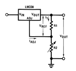
The wiring is like
LM338.png
R1 should maintain a minimum current when there is no load connected to the output, if the current drops below specs (about 5mA) then the regulation doesn't work correctly and you get a higher output voltage.
The voltage across R1 is about 1.25v so for 5mA you need <250 ohm
 

Yeah, it surprised me as well. The 5mA is actually just the maximum minimum('tis weird) load current according to the datasheet. They say the typical minimum load current is 3.5mA. I might try this with a different power source and some lower resistors and see if I don't get different results.
 

Yeah, it surprised me as well. The 5mA is actually just the maximum minimum('tis weird) load current according to the datasheet

The device has a minimum output current in order to regulate the output voltage properly, like many parameters for electronics devices it is not an exact number but a range that may depend on several factors, that range has a minimum , a typical value and a max value.
It's a good idea to do the calculation based on the max value because it is the "worse" value in this case and using it will ensure that the device will also work correctly with the typical or min value.

Apart from that parameter the connection scheme you have described is not correct, unless you mistyped something.
 

Yes, I just tested the new circuit and it produced the same results. My first post is incorrect, I did mean to say that I hooked a resistor from OUT to ADJ instead of PWR to ADJ. Instead, I used two 100ohm resistors and I hooked them from OUT-ADJ and from GND-ADJ, PWR-IN, and then tested and got 6.10V as well.
 

That still isn't correct. One resistor goes from OUT to ADJ and the other resistor goes from ADJ to the ground (negative) side of the supply. You should also add a capacitor between IN and ground to ensure stability or the voltage may be wrong anyway. I think the reason why the manufacturer suggests 240 Ohms for the OUT resistor is it passes 5mA and therefore meets the minimum load current without anything else being connected to it but the value can be higher if something else is drawing current instead.

If that doesn't work, check you have the IC connected the right way around. Assuming you are using the plastic package with a metal tab (TO-220) and you have the plastic side facing you and the pins at the bottom, the connections are:

left - ADJ
middle - OUT
right - IN

Also, the metal tab is connected to the OUT pin so don't screw it down to any other node.


Brian.
 

The way you explained how to set up the circuit is how I set it up. I went through and checked all my connections and made sure everything was correct again and it is just like the schematic shows in the datasheet. I put a 1uF tantalum capacitor on the input side which is what the datasheet recommends. The output was higher this time, approximately 7.5V.

Let me explain again how I set the circuit up and tell me if this is correct.

Positive to the input pin on the right side of the LM338.
Tantalum capacitor connected to positive and ground.
220ohm resistor(changed the value) from adjustment pin on the left to ground.
220ohm resistor from output pin in the middle to adjustment pin on the left.

These directions are with the voltage regulator front facing me. I took the heatsink off of it to make sure it wasn't touching the other resistors.

The input is from a transformer and goes to a KBL406 bridge rectifier. Measuring the voltage, it turns out to be approximately 22V.
 

You seem to have it wired up correctly, the output voltage should be just over 2.5V (2.511V assuming normal current through the ADJ pin).
I can only think of two other things to try before condemning the LM338:

1. try adding a further capacitor across the 1uF you already fitted. If the voltage changes you either have instability problems or the main reservoir capacitor after the bridge isn't working properly.
2. try connecting a 1K resistor across the output. The voltage shouldn't change (it SHOULD be 2.5V anyway), if it does, let us know what it changes to as it will give an indication of whether leakage is an issue.

Brian.
 

Adding the 1K resistor, the voltage changes to 5.74V. I added about 4 or 5 more ceramic disc capacitors that were about 220pF. I didn't have any that were bigger. The voltage stayed the same when I added the capacitors.

Does that conclude that it is defective? Shouldn't the voltage stay the same and the current increase instead?
 

This capacitors are far too small to make any difference so that test isn't really telling anything.

The IC is a voltage regulator though so if everythng else is OK, it should maintain a constant voltage under different loads. I may be wrong but it looks like the LM338 is either faulty or at least out of specification but please try larger a larger capacitor before junking it.

Brian.
 

Oh I don't plan to junk it. Just set it aside until I get a new set and that way I can compare them to something else. I like your ways of debugging though, they never popped into my mind; I was just making an assumption that it was defective. I did put a 16V electrolytic capacitor in the input and it outputted 11V instead but quickly became hot.
 

If you connected a 16V electrolytic across your 26V input voltage I would say you are lucky not to have a big bang!

The fact that a component that does not conduct DC connected to it makes the voltage change points to instability though. I suggest 10uF (rated at more than 26V !!) is connected between the input pin and ground and you connect another one between the output pin and ground as well.

Brian.
 

Layout is important too. You can't build this on a breadboard with long wires all over the place and expect it to work,
 

Almost every circuit in National Semi's datasheet for the LM338 shows 120 ohms from the OUT pin to the ADJ pin (for 10mA when there is no other load).
Then why is everybody in this thread using 220 or 240 ohms which is used with the more expensive LM138?
 
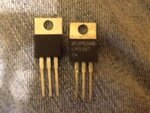
image.jpg
I finally got my others in and switched out the old voltage regulator with the new ones and it reported 1.25V correctly this time. So I guess it was a case of defective items. The weird thing is that I bought a package of 5 and all of them were defective. I bought some more shift registers from the same person and this could be a way to experiment if its the supplier or just a case of faulty ICs. Attached is a picture of the two voltage regulators. The one on the left is the faulty one. The information isn't printed well on it, but it says:
"JM14RG
LM338T P+"
Not sure what the p+ means but it's on the left side on the newest voltage regulator I bought. Just figured I would contribute my results for anyone else that has the same experiences.
 

Status
Not open for further replies.

Part and Inventory Search

Welcome to EDABoard.com

Sponsor

Back
Top