myfaithnka
Advanced Member level 4

- Joined
- Nov 5, 2010
- Messages
- 106
- Helped
- 2
- Reputation
- 4
- Reaction score
- 2
- Trophy points
- 1,298
- Activity points
- 2,022
Hi all,
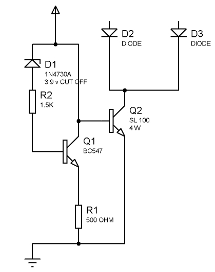
any one pls help me finding the equation for frequency here in this ckt.

i have changed the turns of the feed back,ended up burning that two transistors.
Pls help.
any one pls help me finding the equation for frequency here in this ckt.
i have changed the turns of the feed back,ended up burning that two transistors.
Pls help.