Continue to Site

Welcome to EDAboard.com

Welcome to our site! EDAboard.com is an international Electronics Discussion Forum focused on EDA software, circuits, schematics, books, theory, papers, asic, pld, 8051, DSP, Network, RF, Analog Design, PCB, Service Manuals... and a whole lot more! To participate you need to register. Registration is free. Click here to register now.

frequency doubler using gilbert cell

Status
Not open for further replies.

kripacharya

Banned
Joined
Dec 28, 2012
Messages
1,204
Helped
182
Reputation
360
Reaction score
175
Trophy points
1,343
Location
New Delhi
Activity points
0
I have a 3rd overtone 52.416Mhz crystal (salvaged from an old modem board), and I have the workhorse SA612 gilbert cell mixer ic.

Wanted to make an oscillator of >100Mhz, so I also saw this note AN-1983 where an f x2 method is described near the end.
ne602 frequency multiplier.JPG

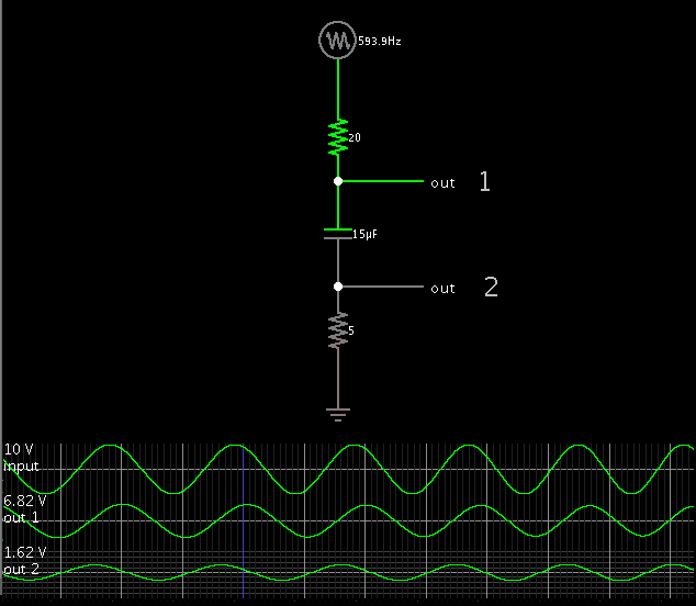
Now i have the 3rd overtone part working on a breadboard (butler config), but somehow just can't understand how the author in the App Note gets a 90deg phase shift using the R and C feeding the signal back into pin 1.

And of course the output (pin 4) stays rock steady at 52.416Mhz with nothing else visible.

Anyone with insights on how to do this ?
 

A capacitor can provide both leading and lagging phase shifts, depending on where you take the output.

There will always be a 90 degree phase differential between capacitor voltage and capacitor current.


As for the article, Fig. 13 is vastly oversimplified. It is more like a conceptual flowchart. It does not show all the components.

Fig. 14 is described as a Colpitts oscillator. It is possible to adjust values so that the LC tank loop is swinging at a greater amplitude than the supply V. This must be a key factor which allowed the author to obtain a 2nd harmonic which was stronger than the supply V.
 

....
As for the article, Fig. 13 is vastly oversimplified. It is more like a conceptual flowchart. It does not show all the components.

Fig. 14 is described as a Colpitts oscillator. It is possible to adjust values so that the LC tank loop is swinging at a greater amplitude than the supply V. This must be a key factor which allowed the author to obtain a 2nd harmonic which was stronger than the supply V.

fig 13 is of course conceptual. I was talking about the setup in fig.14 which is stated to be a practical implementation. But it just shows an R and C in series.

The gain of NE602 is ~15dB, and will be the gain on the input signal level. The system described does NOT work by using a 2nd harmonic. There would be no 2nd harmonic in the applied signal since it is crystal derived. Instead it talks of mixing a freq F with itself, shifted by 90 deg. Result - components are at 2xF and (F - F =) 0 or DC.

What I want to know is how to design the phase-shift RC network @52Mhz which doesn't load the oscillator tank etc etc.
 

True, for there to be a phase shift, there needs to be a complete path (or loop) for the current which is going through the capacitor and resistor. That is the only way the RC time constant can operate.

That is why my simulation needed resistors to ground. Otherwise I could not get a phase shift.

However we do not see a complete path in Fig. 14. It would appear that the series RC passes the waveform with no phase shift.

I wonder if there a chance the IC provides an internal path to ground, to fulfill this requirement?

As it turns out however, there may not need to be such a path. Two similar sinewaves, when multiplied, will always double the frequency... regardless of any phase difference between them.

1372704200_1384871597.png


However it is convenient if there is a 90 degree phase difference between them. Then the output is centered at 0 V.

1352066400_1384871650.png


But suppose the IC blocks DC internally? Then the waveform is centered at 0V, the same as if there had been a 90 deg. phase shift.

Could the author have mistakenly believed the series RC was doing the job, even though it was not?
 

The input impedance of NE602 is ~1.5K to ground.

Even so, a practical value of C with an R cannot give 90 shift at frequencies like 52 Mhz
And i am unable to work out a (simple) network which would do so, and not load the oscillator output.

Yet the author seems to feel it is perfectly easy and feasible to do so.
What am i missing ?
 

You are correct about a 90 deg. shift not being practical at that high a frequency, with a 1.5k series resistance present.

Brief articles such as this often leave out some details, such as how to overcome hurdles that crop up in certain situations.

I would not be surprised if the diagram shows how the author's setup worked at some lower frequency. He observed there was a 90 degree phase shift.

Perhaps he did not use an external resistor. Perhaps he drew the resistor so as to represent the IC's input impedance.

Then he would have dialed up to a higher frequency. (The article states his setup can multiply frequencies as fast as 600 MHz.) It continued to work. Seeing this he probably assumed the phase shift remained at 90 degrees. In reality it would have been less and less, as the frequency went up.

Regardless of a phase difference, or lack of it...

The two similar sinewaves produce 2 * f when multiplied. This is proved mathematically in my first plot, post #4.

Even though it generates a DC component, I imagine the IC would be designed to eliminate that internally.
 

So no obvious solution then hah ?
A bit surprising, considering this is an excerpt from a Philips App Note.
 

... but somehow just can't understand how the author in the App Note gets a 90deg phase shift using the R and C feeding the signal back into pin 1.

I don't think it actually says that. It says:

Figure 13 shows the mathematical model of the frequency
multiplier for doubler applications. The DC offset can be
reduced to zero
by providing a 90 degree phase shift in one of the
legs to assure a SIN(0) rather than COS(0) term.

It then goes on
Figure 14 shows a practical NE602 frequency doubler circuit.

While it says that fig 14 has "phase shift" it doesn't claim to be 90 degrees and it never can be with that configuration.

Keith
 

Yes i saw that too. That was exactly my point, I thought I was missing something someplace.
And since the 2 sentences were so close together, it's easy to make the mistake that they were related.

Now my 2nd point - I tried the config with Osc signal fed back to pin1. Attenuated of course, but only marginally phase shifted.
But I could not see any 2xF components on the output.
Maybe I'll try it again with an improved setup and report back what I find.
 

Are you using the differential output? I did a quick simulation of a bipolar Gilbert cell mixer IC I designed a while ago and you get massive clock feedthrough if you don't look at the difference between the two outputs.

Keith
 

Attachments

  • Mixer 2 double.pdf
    36.6 KB · Views: 114

Status
Not open for further replies.

Similar threads

Part and Inventory Search

Welcome to EDABoard.com

Sponsor

Back
Top