-CAM-
Newbie level 5

- Joined
- Sep 25, 2009
- Messages
- 10
- Helped
- 0
- Reputation
- 0
- Reaction score
- 0
- Trophy points
- 1,281
- Activity points
- 1,353
Hi,
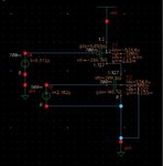
i'm working on this simple circuit to understend better poles and zeros.
**broken link removed**
I wasn't interested in the bias point so T1 is in triode region and T2 in saturation region.
V4 has AC magnitude of 1 V, so i plotted Bode diagram of the output.
**broken link removed**
It seems there is a RHP zero @ 440 Mhz and a pole @ 2.75 Ghz but I don't understand why using formulas with Cadence calculated parameters, i have different results.
Capacitance values are:
T1
Cbd -173.9f
Cdb -71.81f
Cdg -474.9f
Cds 150f
Csg -494f
Csd 144.9f
Cgd -367.7f
Cgs -629.5f
T2
Cbd -9.981a
Cdb -22.87f
Cdg -143.1f
Cds 137.4f
Csg -204.7f
Csd 4a
Cgd -28.49f
Cgs -410.8f
I used the following formulas:
z = gm1/Cgd1
p=-(gds1+gds2)/(Cds1+Cdb1+Cds2+Cdb2+Cdg2)
Can someone help me?
Thanks


