Continue to Site

Welcome to EDAboard.com

Welcome to our site! EDAboard.com is an international Electronics Discussion Forum focused on EDA software, circuits, schematics, books, theory, papers, asic, pld, 8051, DSP, Network, RF, Analog Design, PCB, Service Manuals... and a whole lot more! To participate you need to register. Registration is free. Click here to register now.

Free Wheel Diode in 3 phase motor

Status
Not open for further replies.

ata90

Member level 5
Joined
Apr 13, 2009
Messages
89
Helped
1
Reputation
2
Reaction score
1
Trophy points
1,288
Activity points
1,945
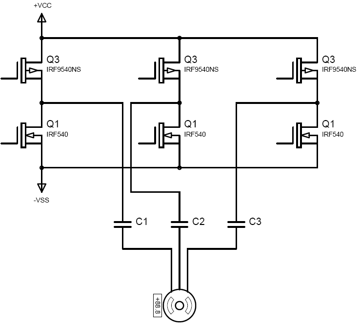
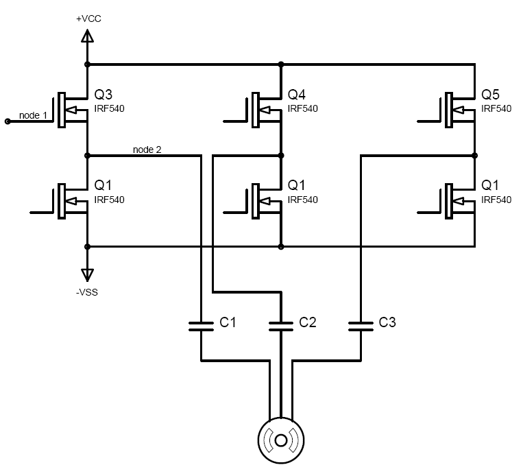
According to figure 1, when we want to run single phase motor, we use free wheel diode along to motor. but according to figure 2, if we want to use 3 phase motor, is it necessary to use FWD? if so, where should we place it? ( it's not possible to place it along 2 phase of motor)


for R-C Snubber see this web page :
Redirect Notice

in your suggested website, there is no schematic diagram of any circuits. how should I implement snubber in my design?
 

Hi.
Your circuit is not practical because of that , your single motor circuit should be DC motor, not ac, and in your 3 phase circuit , you wanna use half bridge topology. in half bridge you should use a negative voltage in source of your below mosfets.(-vcc) to make a ac waveform. and you should use eliminator filter in preceding of your motor. and good mosfets have a schotky diode in parallel with Drain to source junction(internal) in is enough .
 

Ya Dear Goldmith,
sorry, you are right.
 

@GoldSmith:
1) a thing is important is voltage between VCC and VSS, it's not important which VSS is negative, zero or positive, a thing we should consider is VCC > VSS.
in my circuit topology, square wave is varied between VCC and zero. motor doesn't have common node ( i mean middle node that is connected to ground)
have you ever worked with Brushless DC motors? these motors have similar topology.
2) what's eliminator filter?
 

Hey buddy
Hi
Your out put voltage (in 3 phase circuit) should being alternative(AC) my mean is with +vcc and zero you cant obtain a AC as well as. but you can shift it(with capacitor)(after amplification your square wave) .you should know that in Half bridge converters When we want ac out put we should have +vcc and -vcc or +vcc and one capacitor that is serial with your load . single supply can work, but its better to use double supply


SO about your 2nd question. eliminator filter: you know an square wave has a wide spectrum ( my mean is harmonics)
for example your motor is designed for 50HZ but when you give square wave to your motor , many frequencies supply your motor not just 50HZ . you should know that In DC motors at low powers we have not this problem(because the motor.JPGy have large XL) but in ac motors we need eliminator filter.
 

Dear GoldSmith

1) about eliminator filter, as i understand, this filter just keep specified frequency and eliminates other harmonics. so its input is square wave form and its output is sine wave form with specified frequency. am i right?
2) Please see below shematic. do you mean something like this?


3) I saw your preferred shematic. all of your transistors are N-MOS. I have seen that designers use three P-MOS above, and 3 N-MOS below the driver circuit. how do you justify that Vgs is enough for turning ON for 3 trasistors which are located above the circuit? ( in these transistors source voltage is not constant, because of that usually P-MOS is preferred )
 

My friend
Hi
you should avoid to use p mos and n mos in one circuit, because at complementary mode if your supply being 200V you should get 215 volt as 1 and zero volt as 0 . youe can use complementary mosfets when you have level shifter or when you have supply as 15 volts. but you can see p mos and nmos at books but those are not practical those are just to introduction a topology !

In a Pmosfet/Nmosfet pair you can use a simple voltage shifter to drive the P mosfet but in a Nmodfer/Nmosfet pair you need to use bootstrapping or an isolated power source to drive the high side switch.
The Pmosfet is easier to drive as a high side switch but compared to a Nmosfet it is more expensive and has higher resistance (Rds-on), that is the reason that you will usually see all Nmosfet drivers

Alex
 

see my new attachment please:good idea.JPG
look at m2 situation. if you want to m2 going to saturation mode if you match its gate to the ground , m2 going saturation.
bt if you match its gate to +15v to turning of , you will see that m2 is on yet! its analysis is simple! 15 v per 200v is more negative.thus you should give 215 volts to the gate (different between 200 and 215 =15 thus mosfet going off.
you should learn that in all switching circuits use one type of switches . just p type or just n type! because their characteristics are like themselves!
in my first circuit , you can control your switches very simple with 0 volt and 15 volts!
 

you can find n mosfets at high current and high voltage types ! in low prices!

---------- Post added at 16:05 ---------- Previous post was at 16:03 ----------

dear friend ! your idea about eliminator filter (number one ) is correct.
if you want i can give you a prefect schematic to obtain your aim.

---------- Post added at 16:07 ---------- Previous post was at 16:05 ----------

Thank you alex for your guide!
 

Dear GoldSmith and Alex

Thanks for your nice guidance
Now, please assume circuit below:

1) Assume VCC = 15V, and we need Vgs = 10V for turning on the upper arm N-MOS. so (node1 - node2 = 10V). actually the voltage of node 2 is not fixed and it may have any voltages. so how will you adjust the voltage of node 1 in order to have 10 V between node 1 and node 2 !?
2) Is there any solution in order to replace Ground with -VSS?
3) How do you calculate the value of c1, c2 and c3? if we use them, do we still have square wave form in the Motor input? don't these capacitors limit the current of Motor? ( Motor is 3~10A )

Dear GoldSmith, I think a perfect schematic can distinguish as well.
Thanks in advanced
 

To provide a Vgs of 10v you can either provide 10v from an isolated voltage source or use a bootstrap circuit to generate a higher voltage and use it to drive the gate (or an external voltage pump to generate the voltage).
In the isolated supply method it is like having a battery, suppose a 10v battery, you connect the minus pole to the mosfet source and the positive to the gate, in that case the gate will always have a Vsource+10v voltage and the Vgs will be 10v

The bootstrap method charges a capacitor to the supply voltage level and then when the high side mosfet turns on the capacitor voltage works again like a battery to provide to the gate the source voltage + Vcap so the proper Vgs is accomplished.

Your capacitors are in series with the motor (load), I don't think that this can work properly.
A negative supply can probably be used but ? haven't done anything similar and I don't see the point, also the driver of the lowers side mosfet would become more complicated

Alex
 

@Alex:
if ask some solutions for replacing Ground with -VSS, it's because of that I have single supply. maybe I should shift controller part approximately VCC/2.
I know bootstrap technique, however I'm not familiar with isolated voltage source. can you take an example or leave some schematic from isolated voltage source?
 

An isolated power supply is just a power supply that is floating and doesn't share the same gnd as the rest of the circuit, this way the reference of this source can be connected to the high side mosfet source and actually be added on what ever voltage exists there and this creates the Vgs
What I describe is like this
nmosfet_high_side_correct.gif


I haven't used anything like that, but it is similar to a transformer coupled gate driver
**broken link removed**

Alex
 

Status
Not open for further replies.

Similar threads

Part and Inventory Search

Welcome to EDABoard.com

Sponsor

Back
Top