Continue to Site

Welcome to EDAboard.com

Welcome to our site! EDAboard.com is an international Electronics Discussion Forum focused on EDA software, circuits, schematics, books, theory, papers, asic, pld, 8051, DSP, Network, RF, Analog Design, PCB, Service Manuals... and a whole lot more! To participate you need to register. Registration is free. Click here to register now.

FPC antenna for 2.4GHz ISM band - the better option?

Status
Not open for further replies.

chris_la

Newbie level 2
Newbie level 2
Joined
May 9, 2014
Messages
2
Helped
0
Reputation
0
Reaction score
0
Trophy points
1
Visit site
Activity points
28
Hi!

I am new here and this is my first post! I have looked around on the forum for info on FPC antennas, but have not found the info I need. I am thankful for guidance on the subject!

I am from time to time designing devices with Bluetooth functionality. I have always used printed circuit antennas (in rigid PCB) or chip antennas in these designs without really taken the time to look into whether an FPC (flexible printed circuit) antenna could be a better option.

I have seen 2 types of FPC antennas:

1) antenna assembly including coaxial cable and connector. There are many off-the-shelf antennas of this type available. Quite expensive compared to most chip antennas. Examples:
**broken link removed**

2) antenna that is just a piece of FPC without cable or connector, and that is connected to PCB via c-clips. Example in attached figure. I have not found any off-the-shelf antennas of this type. Looks like it should be inexpensive. As price is always a heavy factor in the products I am working with this is the type I am most interested in.

Is there anyone here having experience in type 2 above? I would like to get an understanding of when it is advantageous to use the type 2 FPC antenna instead of a chip antenna. A clear advantage is the smaller space required. Are there any more advantages? What are the disadvantages?

How do the type 2 FPC antenna compares to a chip antenna in terms of price and performance? Are there type 2 FPC off-the-shelf antennas available (have not found any) or do they have to be custom designed in order to take into account the surrounding structures?

Thanks,
Chris
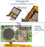

FPC_antenna_2.jpg
 

Are there type 2 FPC off-the-shelf antennas available (have not found any) or do they have to be custom designed in order to take into account the surrounding structures?

It doesn't really matter if the antenna is realized on a flexible board or regular PCB - once it gets really small, the radiation resistance is far away from 50 ohm and the antenna matching becomes very sensitive and very narrow band. These designs are full custom designs, and have to account for the enviroment where the antenna is mounted. There's no way you can get acceptable performance in unknown/arbitrary environment for such a miniaturized antenna.
 
It doesn't really matter if the antenna is realized on a flexible board or regular PCB - once it gets really small, the radiation resistance is far away from 50 ohm and the antenna matching becomes very sensitive and very narrow band. These designs are full custom designs, and have to account for the enviroment where the antenna is mounted. There's no way you can get acceptable performance in unknown/arbitrary environment for such a miniaturized antenna.

I think that your problem is a SYSTEM problem. For short-range Bluetooth operation almost ANY antenna can be used, probably even a quarter-wave piece if a soft wire.
SYSTEM function depends not only on antenna parameters but several other quantities, propagation path and distance, etc.
So use several types of antennas to test your system, then select one giving best results.
 
I think that your problem is a SYSTEM problem. For short-range Bluetooth operation almost ANY antenna can be used, probably even a quarter-wave piece if a soft wire.

Sure you could use lambda/4 and many other designs. But Chris question was about a very small antenna, and that's where things get sensitive.
 
Thanks for the help!

It seems to me the FPC antenna is the better choice (or maybe the only realistic choice) in miniature products. In cases where there is space for a non-FPC antenna, is there any argument or advantage to design in a chip antenna or a printed antenna in regular PCB instead of an FPC antenna?

Chris
 

Selecting preferred miniature antenna performance (bandwidth, gain, efficiency) is seldom the choice of what supporting structure to use. A common reason to use an antenna with size less then lambda/4 is that available space for a bigger antenna not exist.
Probably is then also existing ground-plane very short. What supporting structure to use is then a question about how to use existing space as effective as possible, from antenna view.
If existing PCB ground allows it can it be reused as a part of the antenna, which allows a bigger total antenna structure as it then will be enough to design an monopole antenna, which is half the size of a dipole antenna. These antenna types can be printed on main PCB or be a self-supporting structure. From antenna performance view is best antenna carrier, the carrier that allows best use of existing volume.

Ceramic carrier is another way to reduce physical limits of an antenna while still make it reasonable tunable. Reason to use ceramic material is that it often have higher dielectric constant then air or common PCB materials. High dielectric constant reduces wavelentgh physical size but do that at a cost, such as reduced bandwidth and all ceramic material are somewhat lossy => some RF signal will be lost.
Also other kind of material can be used both for antenna and its carrier. If antenna needs to be very small compared to wavelength do loop antenna offer a flexible adjustable size, to best use existing limited space.
A typical example is for 433 MHz remotes/fob which often have an printed loop antenna that follows the edge of main PCB. Antenna do then not occupy much internal space but that limited space is well used both for internal electronics and antenna.
FR4 material in main PCB is often mentioned as somewhat lossy at higher frequencies, but as long as it not is an super critical antenna, is 2.4 GHz a minor problem. And even if it is, can losses be reduced by printing antenna dual side on PCB and if needed ad air-slits.

One reason to not place antenna on main PCB is if it comes very close to other electronics causing EMI or parts that absorbs RF signals, such as some ferrite cores, battery and LCD displays. This problem is bigger for monopoles compared to dipoles as for an monopole antenna is RF current superimposed over existing ground currents by design. It can cause many kinds of problem such as malfunction of low frequency logic or reduced radio performance, but it is nonetheless a common solution for compact embedded antennas, which in most cases works ok.

If coaxial cable is possible to use between antenna and main PCB, do I not see it as an extreme small structure. Reason for or against coaxial cable, is mainly related to the need to route RF signal between radio circuit and antenna.
Also use coaxial cable as part of antenna, do often results in pore result. Not because that it not work good but because that kind of solutions often is used by designer that not have tools to verify or knowledge about what placement restrictions that limit a such coaxial cable.

Best antenna, is the antenna that fits your needs for the total circuit functionality.
 
Last edited:
Status
Not open for further replies.

Part and Inventory Search

Welcome to EDABoard.com

Sponsor

Back
Top