Vermes
Advanced Member level 4
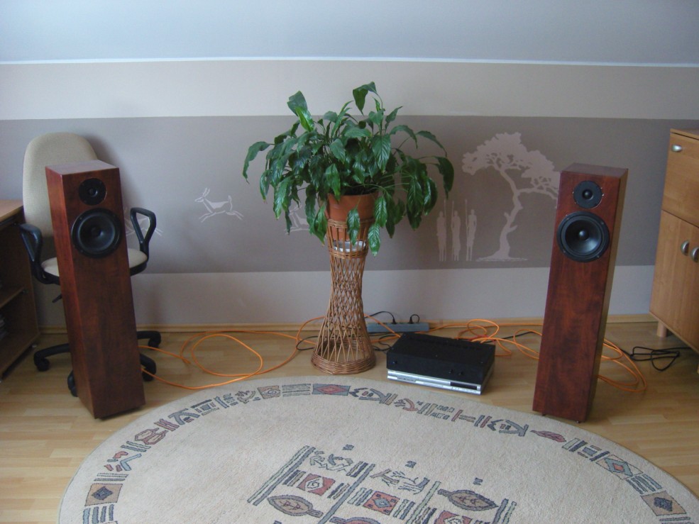
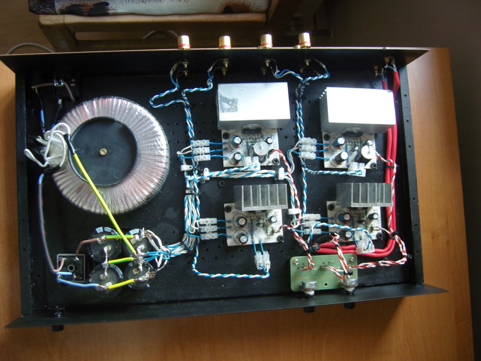
It is a four-channel amplifier based on LM3876.
Supply:
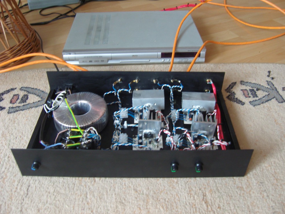
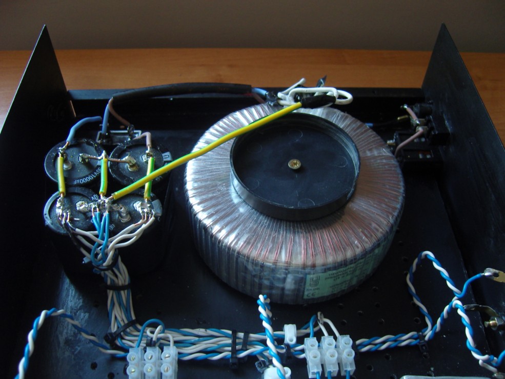
- 2x24V transformer, after rectifying 35V, 250VA
- rectifier bridge 25A
- capacitors 4x10000uF
- fuse 3,5A
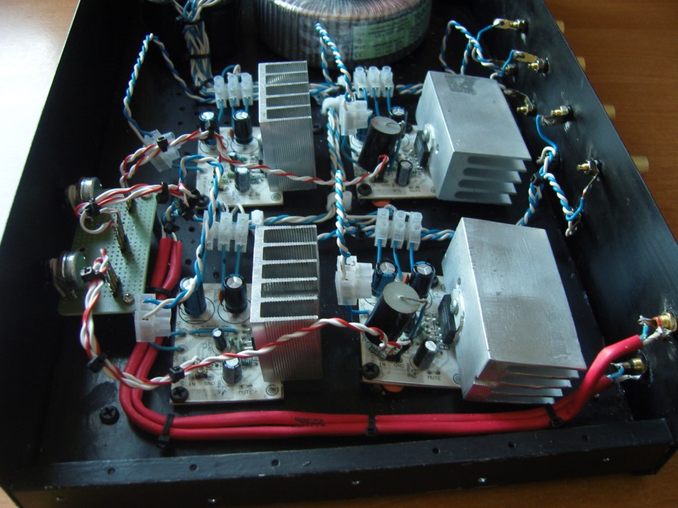
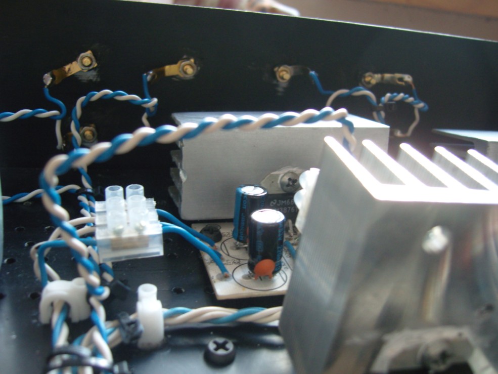
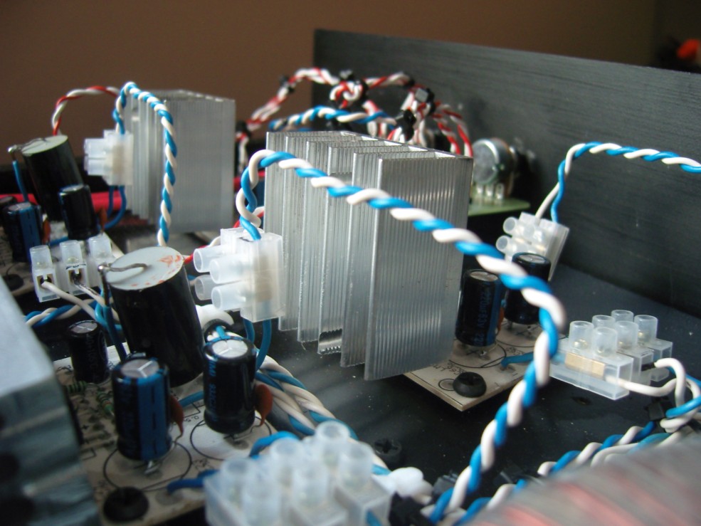
Supply on PCBs is filtered by 220uF capacitors from Jamicon and normal 100nF. Supply cables are made of 1mm copper cable.
Audio signal:
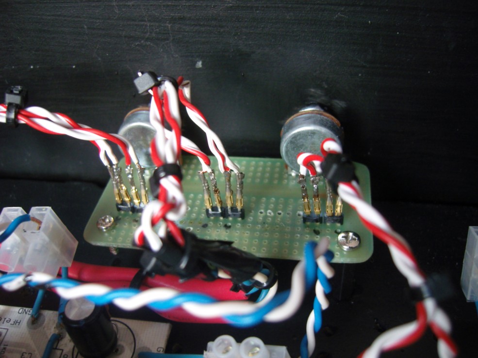
Ground connects with the housing at chinches, then signal passes to the potentiometers through shielded cables (shield connected only from one side). Near potentiometers (10kohm), grounds are still led separately. Cables going to the PCB are made of 0,5mm copper twisted pair. Applying shielded cables caused difficulties in implementing a connection to the sockets. Shielded cable is very rigid, so it was replaced in that place with the twisted pair.
Separate potentiometers were an intended solution. It solves the problem of differences between channels in double potentiometers, and volume of left and right speaker can be set.
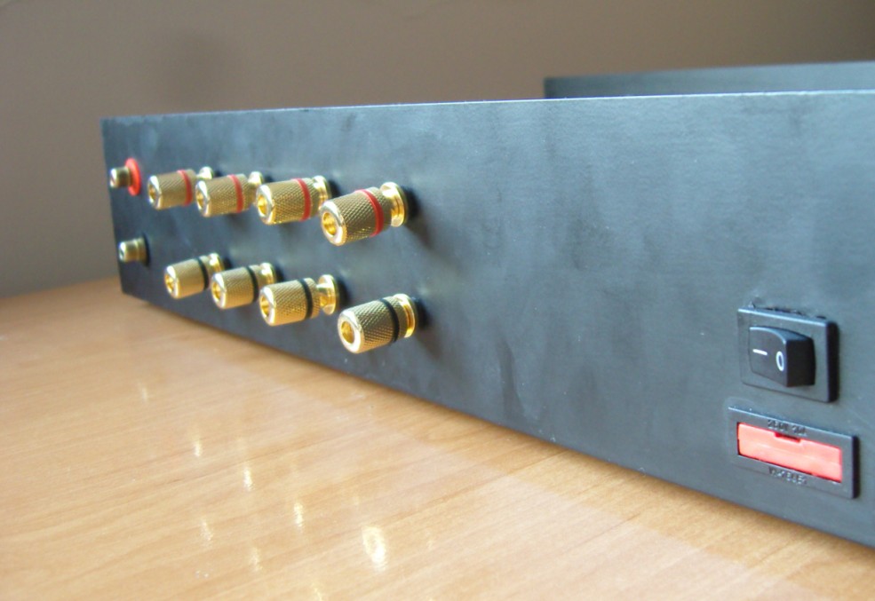
Output signal is led to banana sockets by 1mm cables.
Filters:
There are not crossovers in the speakers. Instead of that there is a capacitor before the twitter as a necessary component protecting the speaker against burning. 2.7uF capacitor disconnects the speaker with a slope of 6dB oct. There is no capacitor at the input. Treble section is quieter in comparison to the bass section – resistor at the input in the PCB is 2kohm, while in bass section it is 1kohm.
Low-pass filter is placed before the amplifier, in place where the signal enters the PCB. It disconnects the woofer with a slope of 6dB/oct. It consists of a serial 22kohm resistor and parallel 5nF capacitor. Protection capacitor at the input (3,3uF) was left.
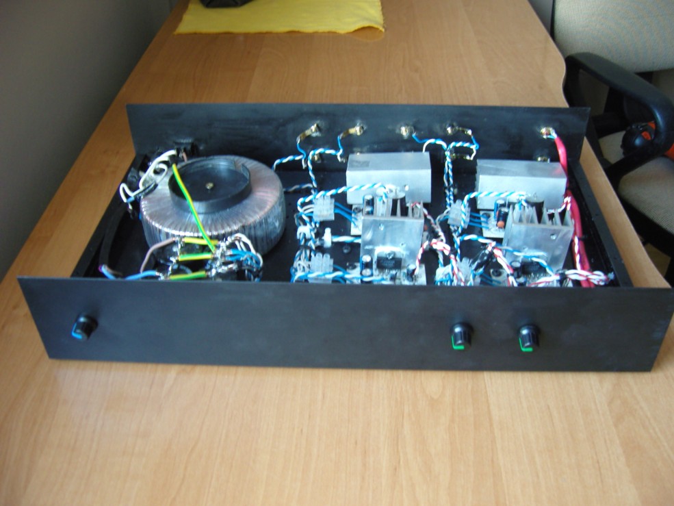
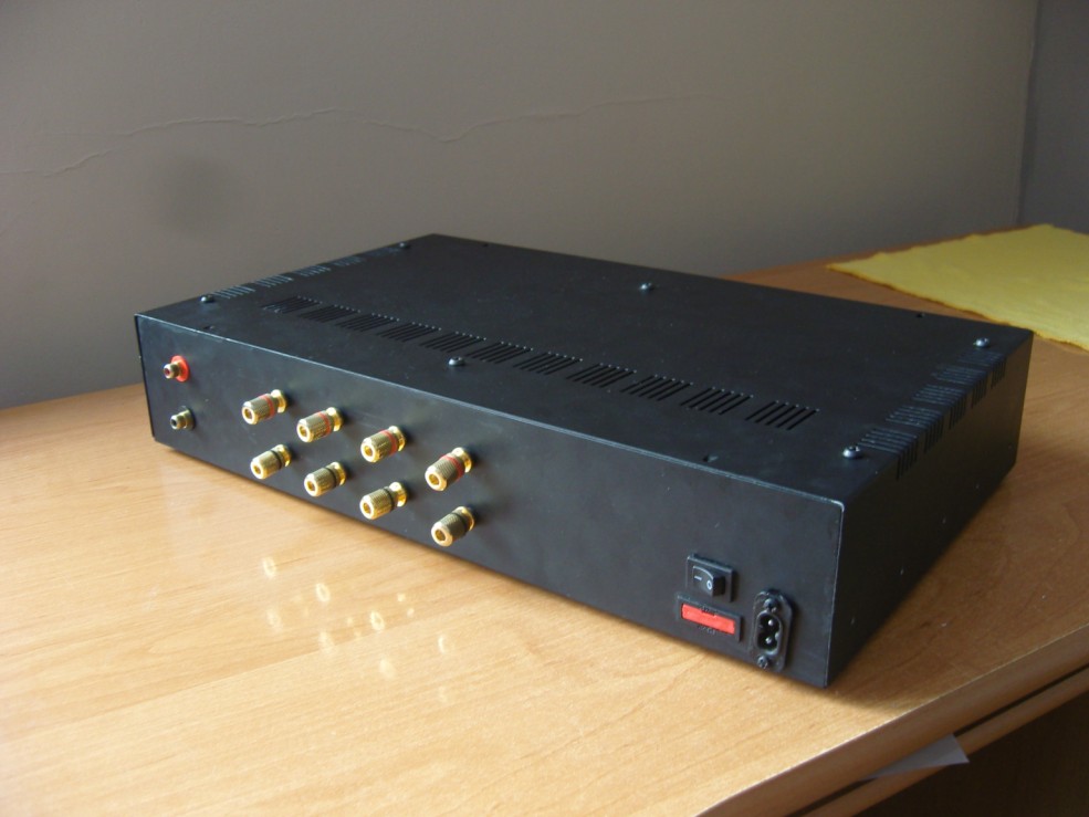
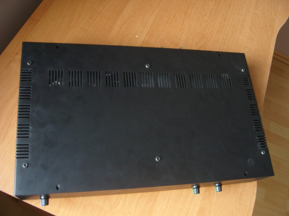
Housing:
Universal housing T442 was used. It needs to be modified a little due to its profile (shape of side walls). The plate is so thin, that the top wall of the housing has to be strengthened.
Components used:
- transformer
- supply capacitors
- bridge
- housing
- LM
- PCB
- components for the PCB
- potentiometers
- sockets


Link to original thread - Wzmacniacz 4 kanałowy na LM3876 (system quasi-aktywny)