Continue to Site

Welcome to EDAboard.com

Welcome to our site! EDAboard.com is an international Electronics Discussion Forum focused on EDA software, circuits, schematics, books, theory, papers, asic, pld, 8051, DSP, Network, RF, Analog Design, PCB, Service Manuals... and a whole lot more! To participate you need to register. Registration is free. Click here to register now.

formula convertion problem

Status
Not open for further replies.

dope40

Member level 4
Member level 4
Joined
Oct 3, 2011
Messages
76
Helped
0
Reputation
0
Reaction score
0
Trophy points
1,286
Location
Bulgaria
Visit site
Activity points
1,777
Hi so i have this formula AFR = V*0.228+0.70 .. Where V is the adc value in volts , but i dont know how to convert it into volts and use it in the formula.
 

if u using 10 bit ADC then read is between 0 to 1023 right. so 0 is 0V and 1023 is 5v . if configuration is correct. so 2.5v if adc value is 511.5. so put this voltage to your equation .
 

Just multiply the adc read value with the step size.V=Stepsize*adc read value (mV)
Step size can be calculated by
step= ADC Vref/2^adc resolution.
if you are using 10bit adc and Adc vref=5V then
step=5/2^10 mV=4.8mV
 

Thanks i figured it out , and now it works , but now i have to figure out how to display it on 3 7-segment displays . For example if i get AFR = 14.7 and break it down to 1, 4, 7 how do i multiplex it on to the 7-segments, so that the first = 1 second = 4 .. etc. ?
 

turn off all digits.
Assign SSD mask equivalent to 1 to SSD data port and turn ON digit1 for 5 ms then turn off all digits.
Assign SSD mask equivalent to 4 to SSD data port and turn ON digit2 for 5 ms then turn off all digits.

repeat continuously
 

What compiler are you using?

https://embedded-lab.com/blog/?p=2086

Common Cathode Masks

0 0x3F
1 0x06
2 0x5B
3 0x4F
4 0x66
5 0x6D
6 0x7D
7 0x07
8 0x7F
9 0x6F

Common Anode Masks

0 0xC0;
1 0xF9;
2 0xA4;
3 0xB0;
4 0x99;
5 0x92;
6 0x82;
7 0xF8;
8 0x80;
9 0x90;

digit[] contains number split and it is char type
CA[] or CC[] contains masks and is also char type

SSDPORT = CA[digit[x]];
 

Here is the code i have menaged to write so far ....
Code:
unsigned short one, two, three ;
unsigned char ch;
unsigned int adc_rd;
long tlong;


void main() {
    INTCON = 0x20;                      // All interrupts disabled
    ANSEL = 0x04;                    // Pin RA2 is configured as an analog input
    TRISA = 0x04;
    ANSELH = 0;                      // Rest of pins are configured as digital
    TRISD = 0;
    TRISE = 0;


    ADCON1 = 0x82;                   // A/D voltage reference is VCC
    TRISA = 0xFF;                    // All port A pins are configured as inputs
    Delay_ms(500);


    while (1) {
      adc_rd = ADC_Read(2);

        tlong = ((5000/1023)*(long)adc_rd)/10   ;
        tlong = (tlong*2)+1000;
        one = tlong / 1000;
        two =  (tlong / 100) % 10;
    }
}

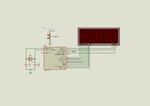
and here is the circuit ......
12.JPG
 

What should it display, Integer or real value? What type of display is used, CC or CA?, The circuit is incomplete. You need NPN/PNP transistors to enable/disable the segments. It can't be guessed from your circuit. Zip and post mikroC project files + Proteus file.
 

Status
Not open for further replies.

Similar threads

Part and Inventory Search

Welcome to EDABoard.com

Sponsor

Back
Top