Continue to Site

Welcome to EDAboard.com

Welcome to our site! EDAboard.com is an international Electronics Discussion Forum focused on EDA software, circuits, schematics, books, theory, papers, asic, pld, 8051, DSP, Network, RF, Analog Design, PCB, Service Manuals... and a whole lot more! To participate you need to register. Registration is free. Click here to register now.

fm transmitter losing lock when increasing the output power

Status
Not open for further replies.

Nermin

Newbie level 6
Joined
Apr 29, 2016
Messages
14
Helped
1
Reputation
2
Reaction score
1
Trophy points
3
Activity points
115
Hi there. I registered today and this is my first thread here. I see that you guys do the help all the time, so my guess is that I will get some help too.

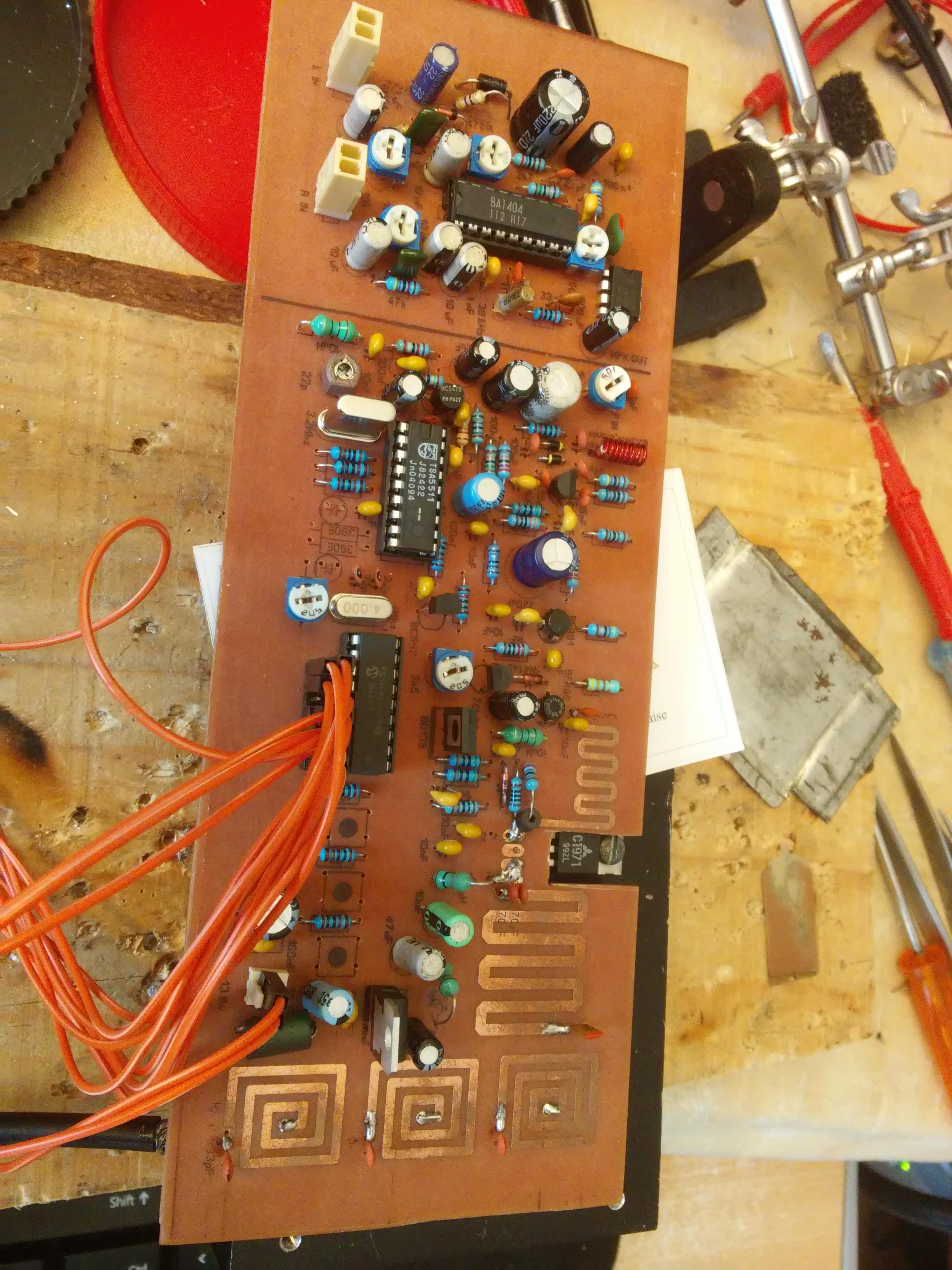
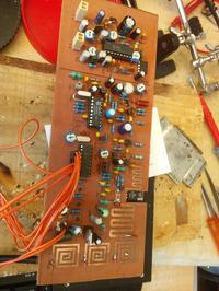
I recently completed fm transmitter ( no tune RDVV ) and I have problem because it is losing lock when power is more than about 0,5 W approximately. Frequency counter says that when it lose lock it goes to frequency about 82-84 MHz. When output power is at small level everything is just fine.

So, probaly some RF field making some problem on board? Dont know now!

Transmitter is very well known design, with tsa5511 and pic16F84. VCO is based on FET j310, buffers are bfr91 and bfr96 and output is 2sc1971.
Only thing that is different from original design is that I placed ba1404 stereo encoder on same PCB, but that should not be the problem. ( probably)

Any guess?

Many thanks bye for now.
 

The problem is most probably due to unwanted RF feedback into the PLL circuitry. Try to keep that bundle of red wires away from the RF power stage. Even better maybe to use a multi-core shielded cable to help keep any RF out of sensitive areas.

The BA1404 is a terrible stereo encoder but will not cause the problems you are having.
 

Is that problem happening whichever the position you lean the board ? I mean, can you determine whether occur an improvement or aggravation of the iterference effect if the FM transmitter is placed close or apart from any stuffs ? In my opinion, you are also facing to issues related to the layout design of the board. As a simple test to check how much of eletromagnetic field are being scattered you could put a metallic grounded plate as close as possible from the bottom side of the board. A priori, this should shield part of the EMI, allowing you to increase the output power – at least in theory.
 

Hello guys, thanks for replies. Yes, most probably the problem is unwanted RF somewhere in the PLL loop. I have built few of these transmitters (not no-tune versions like this one on image) and this is the first time to deal with this kind of problem, but I guess that is the RF magic, right. That bundle of red wires is for LCD. Problem is there with or without them.
When we speak about stereo ba1404 can you give me a better solution in one chip version? ( njm2035, bhf1415 or something else)
Problem is the same when moving the board, which means that problems comes from inside the board, not from outside.(I guess that was point of andre_luis).
Only thing that I can try more is wait for the metal enclosure for this transmitter and see what is happening then. As you can see on the image, this is the one side PCB, there is no ground plane so maybe that is the catch.
 
As you can see on the image, this is the one side PCB, there is no ground plane so maybe that is the catch.

The grounded metallic plate mentioned above would act as the PCB ground plane.
 

I agree that the BA1404 was pretty bad. That is why it was discontinued and replaced by the much better BH1415, BH1416, BH1417 and BH1418 which I think are also discontinued.
The BA1404 had an RF oscillator which might be causing interference to your new RF oscillator?
 

I agree that the BA1404 was pretty bad. That is why it was discontinued and replaced by the much better BH1415, BH1416, BH1417 and BH1418 which I think are also discontinued.
The BA1404 had an RF oscillator which might be causing interference to your new RF oscillator?

Hello. No, it is not the case. I don't use that part of the chip at all. I just use it as the stereo encoder. Today, ba1404 was even out of its socket when I did some testing, and problem was the same, so we are now sure that its not making troubles.
 

Since you used double sided PCB, why you haven't used GND plane on the Top layer ?? It will decrease the interference problems.
A PLL can be influenced by high power RF signal levels but I don't guess that's the main problem.There might also be wrong calculated PLL loop filter components or a kind of supply interference.I don't think this power level will directly impact the PLL locking.
 

So, probaly some RF field making some problem on board?

But the audio vol control will be after the RF stage and I do not think it audio gain will break the PLL lock!!

Only way the audio section can talk to the RF section is via the power supply. Do you have a "good" power supply? It is also good to put decoupling capacitors at all the ICs. Just separate the audio and the RF power supply with a choke and see the effect...
 

Just using normal (wound) inductors for the on-board 6W power amplifier will solve much of the problems.
This will make the power amplifier to be more compact on the PCB (less occupied space) which makes spreading less RF radiated power, especially on the PLL circuit.
 

Another cause may be a "Pulling Effect" that is coming from input impedance fluctuation of the Power Amplifier.
I mean, if the VCO pulling spec. is so poor AND PLL locking bandwidth is small, a small fraction of impedance changing of the Power Amplifier may result unlock the PLL..
 

Since you used double sided PCB, why you haven't used GND plane on the Top layer ?? It will decrease the interference problems.
A PLL can be influenced by high power RF signal levels but I don't guess that's the main problem.There might also be wrong calculated PLL loop filter components or a kind of supply interference.I don't think this power level will directly impact the PLL locking.

This was not my first one-side pcb of this transmitter. Only difference is that this one on the photo is no-tune version. Other difference is it has printed coils on board instead of wire-coils inductors.
Also, we all know that double side PCB is harder to make than one-sided. Also, I love to use uper side of the PCB for silkscreen. It makes PCB much nicer.
 

But the audio vol control will be after the RF stage and I do not think it audio gain will break the PLL lock!!

Only way the audio section can talk to the RF section is via the power supply. Do you have a "good" power supply? It is also good to put decoupling capacitors at all the ICs. Just separate the audio and the RF power supply with a choke and see the effect...

You probably made a mistake here. We were not talking about possibility that audio making problems.
 

Just using normal (wound) inductors for the on-board 6W power amplifier will solve much of the problems.
This will make the power amplifier to be more compact on the PCB (less occupied space) which makes spreading less RF radiated power, especially on the PLL circuit.

Maybe those printed inductors made from copper are making interference. Now I remember that I saw the photo of transmitter like this that have shielding between those printed coils and rest of unit.
 

Another cause may be a "Pulling Effect" that is coming from input impedance fluctuation of the Power Amplifier.
I mean, if the VCO pulling spec. is so poor AND PLL locking bandwidth is small, a small fraction of impedance changing of the Power Amplifier may result unlock the PLL..

I dont understand this thing with pulling, maybe you are right, but let me explain one thing. First thing I built on board was VCO, J310 fet with its two varicaps. Then I applied about 7 V to varactor ( half of the value of the voltage of the entire unit, which is 13,8 V). Then I did some tweaking with coil and capacitor in oscillator to make VCO working in the middle of the wanted band. In this case it works on 98 MHz. This means that VCO is properly tuned and PLL dont have problems to lock on entire band.
 

So, as I said before, when board gets its metal case maybe this problems will be gone. I am still working on it.
 

You probably made a mistake here. We were not talking about possibility that audio making problems.

Yes, right!! By the time I realized the mistake, it was not possible to correct. Sorry anyway!
 

Hello. Me again after few days. As I said before, I have results after finishing casing for PCB. Results are bad, almost the same like without the enclosure so I am worried and disappointed now.
Quick explanation of the problem: Device loosing lock when power is increased at about 1W and more, Frequency goes down to about 79-80 MHz. Voltage on varactor is minimum ( about 0,7V) .
When power is reduced on previous level, loop activate again by its self and stays stable all the time. Until next increasing of output power off course.

A lot off effort and time is invested in this so I hope that we will find solution. Thanks in advance.
 

Did you check the power supply? I hope it has sufficiently low impedance.
 

Did you check the power supply? I hope it has sufficiently low impedance.
Power supply is fine. Its factory made, 25-30A with regulated voltage up to 16V. I use it all the time.
 

Status
Not open for further replies.

Part and Inventory Search

Welcome to EDABoard.com

Sponsor

Back
Top