Continue to Site

Welcome to EDAboard.com

Welcome to our site! EDAboard.com is an international Electronics Discussion Forum focused on EDA software, circuits, schematics, books, theory, papers, asic, pld, 8051, DSP, Network, RF, Analog Design, PCB, Service Manuals... and a whole lot more! To participate you need to register. Registration is free. Click here to register now.

flyback leakage inductance

Status
Not open for further replies.

phobos1

Full Member level 2
Joined
Jan 18, 2010
Messages
135
Helped
15
Reputation
30
Reaction score
15
Trophy points
1,298
Location
Salem, Tamil Nadu, India
Activity points
2,112
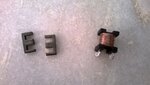
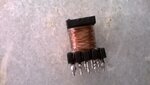
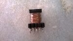
Hello i wound a flyback transformer by hand and i calculated the leakage inductance by shorting secondary windings. the problem is i measure half of the primary inductance as leakage inductance i.e my Lp is 5.6mH and Leakage inductance is 2.3mH. how can i overcome this problem. I have to hand wind my transformer as i have no other go... pls suggest me some tips to reduce my leakage inductance.......


Also pls tell me does this problem reduces the output efficiency......
 
Last edited:

Please post *good* photos of your windings and your complete transformer.
Leakage inductance is reduced by tight coupling of the primary/secondary windings.

Other questions:

What is the operatinal frequency? How did you create the air gap for the desired Lp? What cores are you using? What is the turns ratio?
 

hi
1) I ground the core using a file at the center limb.
2) the turns are primary=168, secondary=19, auxillary=19 and
i made the windings 1/2 primary+secondary+auxillary+1/2 primary
3) 5.6mH is my Lp
3) Using cosmo ferrites EE1605 cores
4) 60Khz operating frequency
5) i have attached the images

note: i used sellotape to insulate between windings..
 

Attachments

  • WP_20131218_001.jpg
    WP_20131218_001.jpg
    350.8 KB · Views: 74
  • WP_20131218_002.jpg
    WP_20131218_002.jpg
    336.7 KB · Views: 72
  • WP_20131218_005.jpg
    WP_20131218_005.jpg
    353.9 KB · Views: 80

Your construction is good. But you can still improve it.

Try making the windings: 1/3 primary; 1/3 primary + secondary + auxiliary; 1/3 primary

Also since you are already winding the primary and the secondary together in the second layer, remove completely the cellophane tape.

Now, you could have insulation problems with this setup. But at least will tell you where the problem lies.
 

That picture looks okay, but it doesn't show the secondary or aux winding, or your insulation, creepage protection, screening, etc...

But even so, assuming your air gap isn't huge, I have to assume those initial measurements are off. It's really hard to end up with such huge leakage so long as your windings overlap. It certainly wouldn't hurt to try a sandwich winding configuration. I would do Aux, 1/2 primary, Secondary, 1/2 primary (from inside out), assuming the aux winding is just for boostrapping the controller power. If the aux winding is for output voltage feedback as well, I might put it in the same layer as the secondary instead (if creepage can be satisfied).
 

Status
Not open for further replies.

Part and Inventory Search

Welcome to EDABoard.com

Sponsor

Back
Top