Continue to Site

Welcome to EDAboard.com

Welcome to our site! EDAboard.com is an international Electronics Discussion Forum focused on EDA software, circuits, schematics, books, theory, papers, asic, pld, 8051, DSP, Network, RF, Analog Design, PCB, Service Manuals... and a whole lot more! To participate you need to register. Registration is free. Click here to register now.

Flux walking detection

Status
Not open for further replies.
The switching frequency is 16kHz. I've choose a 50Hz transformer because it copes better with overloads (2-3 times the rated power) and I don't have to deal with high voltages.
 

Ok, but you don't have any benefit from operating at 16kHz as your magnetics size, volume and weight is that of a 50Hz transformer.
 

The higher the switching frequency, the less are the distortions of the generated sine wave (and the Mosfets conduction losses).

And you still have to filter out those switching harmonics using a LC filter thus a higher frequency also helps to minimize these two components.
 

could you post a diagram of how the four gate signals should look like
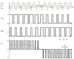
Here's a waveform picture from a power electronics lecture showing unipolar (also called 3-level) pwm

3-level pwm.jpg

Uan and Ubn are the outputs of both half bridge legs, expect respective high and low side gate waveforms (high side similar, low side inverted, some dead-time added). U2 is the resulting bridge output voltage. The first line shows the respective triangle voltage of an analog pulse width modulator.

- - - Updated - - -

Regarding switching frequency discussion, 16 kHz is the minimal value if you want to avoid audible noise, sounds basically reasonable.

The interesting question is how much core losses are caused by the pwm frequent current. High frequent AC flux is only a small fraction of 50 Hz flux, the additional core losses are probably low. Another point to consider is skin effect loss of the most likely massive primary wire.

You can of course add a dedicated LC low pass filter before the transformer, but most designer would try to avoid it.

The preferred todays topology for kVA battery inverters is high frequent DC/DC + high voltage inverter in any case.
 
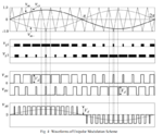
BTW, the image I've posted above (the unipolar SPWM algorithm) belongs to a Texas Instruments datasheet so I doubt the topology is based on a wrong theory.
Would you kindly share the datasheet number? We could study it and offer some additional recommendations.

You will still require a hall-cell type sensor to be able to monitor the transformer's primary current.
Low pass filtering its output will give you essentially the 50Hz +DC component (if any). You may then study what causes it and if your corrective actions do indeed correct the problem.
 

As far as I've read, you basically need two center-aligned sine modulated PWM signals, one of them being shifted by 180 degree like in the diagram bellow:

uni-pwm.png

The main benefit is that the Mosfets are switched at half the output frequency (so I could switch the Mosfets at only 8kHz to get a 16kHz chopped sine wave).

I'm going to rewrite the MCU software to implement this algorithm. Many thanks for pointing me out in the right direction, @FvM!

- - - Updated - - -

This is the app note I was talking about:

https://www.ti.com/lit/an/snva678b/snva678b.pdf

You can find the diagram I have posted above on the page #6 of this app note.

However, they are talking about a "tri level PWM signal" (on the top of the same page) but the description bellow is about the algorithm I'm using for now.

Actually, what @FvM has suggested is this "tri level PWM signal". I must admit I have read about it before but I didn't know about its benefits.
 
Status
Not open for further replies.

Similar threads

Part and Inventory Search

Welcome to EDABoard.com

Sponsor

Back
Top