Continue to Site

Welcome to EDAboard.com

Welcome to our site! EDAboard.com is an international Electronics Discussion Forum focused on EDA software, circuits, schematics, books, theory, papers, asic, pld, 8051, DSP, Network, RF, Analog Design, PCB, Service Manuals... and a whole lot more! To participate you need to register. Registration is free. Click here to register now.

Fluctuating airfoil using stepper motor (not getting the desired frequency)

Status
Not open for further replies.

kbsanjayvasanth

Newbie level 4
Joined
Feb 9, 2023
Messages
6
Helped
0
Reputation
0
Reaction score
0
Trophy points
1
Activity points
51
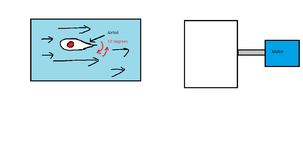
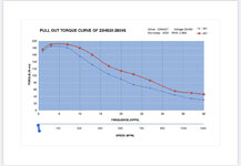
Hi! For my experiment, I am trying to fluctuate (front and back motion) a 3-D printed airfoil using a stepper motor with the capability of 1000RPM (and I use 999 RPM forward and 999 backward) but I'm not getting the desired frequency. This is with a water flow of 50 liters per minute flowing over the airfoil. The max frequency I'm getting is 3Hz. What could be the reason for this? I'm from Aerospace bg so not too familiar with complicated electronic problems. My initial guess is because of the inertia of the rotor in this case. Please correct me if I am wrong.

I have attached a link to the motor that I am using with a stepper motor controller. Stepper motor

Stepper motor controller

Any suggestions could help!
 

Attachments

  • airfoil movement pain image.png
    airfoil movement pain image.png
    17.8 KB · Views: 90

Hi,

Inertia, acceleration, force, torque .... not really electronic topics.
Did you calculate these?
And compare with the stepper datasheet?
--> this should be the first step to debug the problem.

Klaus
 

I did I tried with the motor outside the flow-field as well. It has a torque of 190 N.cm. I saw this chart where it mentions torque vs freq vs rpm. We bought high torque motor to be safer just in case but it makes sense that’s why we are not able to achieve high freq. I have attached the image that I found from the specs. correct me if I’m wrong.
 

Attachments

  • 65869891-3256-4584-9D25-8E3B3C27E2E6.jpeg
    65869891-3256-4584-9D25-8E3B3C27E2E6.jpeg
    230.6 KB · Views: 86

Hi,

post#3 is just information about the motor side.
So again: You have to do accelartion calculations and torque calculations. We can´t do this for you because we don´t have the informations...

Klaus
 

The bigger the motor the more mass you have to shift to move it. Adding the airfoil makes the problem harder, especially as the air flow will require additional power to deflect it.

Also be careful with specifications, when some stepper motors are described as RPM they really mean steps per minute and depending on the step angle, you may need several steps to achieve the 10 degree movement. The motor you show has a 1.8 degree step so at least six steps are needed to reach 10 degree rotation and this obviously limits the top speed.

The other consideration is the controller, the pulse speed is probably a technical rather than practical specification. To drive full load and full speed simultaneously may not be possible and bear in mind that some manufacturers 'stretch' the specification to the limit to make their products sound more appealing!

Brian.
 

While it may sound 'fancy' to use a Stepper Motor, I strongly suggest for your application you should instead use a Servo Motor. They are much easier to control, have a much higher torque in a smaller package, and are actually designed for applications such as yours.
 

While it may sound 'fancy' to use a Stepper Motor, I strongly suggest for your application you should instead use a Servo Motor. They are much easier to control, have a much higher torque in a smaller package, and are actually designed for applications such as yours.
Hey thanks for suggesting, I would prefer a higher frequency/rpm than a higher torque. The mass of the airfoil is very less, and looking at the graph in post#3 lower Torque values can give you a higher rpm and freq. Is that something servo can do?
 

Its not quite clear why you are insisting on high Rpm, since your application is an oscillating one over a relatively small angle. Even a low cost basic servo like this onewould serve (pun intended) your described purpose.

For your "frequency" requirement, you need to see the servo specs for positioning speed - typically mentioned as 0.xx seconds/ 60deg at a given power-supply voltage. If you want even faster, then a simple method using levers & velocity ratio calculations can be used. Here's one of thousands of youtube tutorials.

It is used in applications of RC modeling for surface control all the time, amongst others uses.
 
Last edited:

Buddy, I know servo motors can "also" solve the purpose. I'm looking for a frequency of 50-100Hz. I don't see anything with that high of a frequency. For ex: example servo motor does not have a high freq in my range. Without a load, its max freq is around 8Hz.
 

The bigger the motor the more mass you have to shift to move it. Adding the airfoil makes the problem harder, especially as the air flow will require additional power to deflect it.

Also be careful with specifications, when some stepper motors are described as RPM they really mean steps per minute and depending on the step angle, you may need several steps to achieve the 10 degree movement. The motor you show has a 1.8 degree step so at least six steps are needed to reach 10 degree rotation and this obviously limits the top speed.

The other consideration is the controller, the pulse speed is probably a technical rather than practical specification. To drive full load and full speed simultaneously may not be possible and bear in mind that some manufacturers 'stretch' the specification to the limit to make their products sound more appealing!

Brian.
What you say makes sense Brian. What would you suggest for this application then, I have calculated the torque on the motor to be 57 +/- 5 Newton.cm.
 

This isn't my field of expertise and you haven't given any size of the airfoil to help visualize it. Using the calculation you made, any motor exceeding 62 Newton/cm torque and having a stepping speed of at least 10mS should suffice. For driving it, the cheapest option would be to use one of the many pre-built stepper driver boards sold for building 3D printers and some simple pulse generating software.

If I may make a suggestion, and I'm not sure if it is applicable, have you considered a reciprocating mechanism and standard motor or maybe using a gearing system to convert a wider stepping angle to 10 degrees you need. Both methods might reduce the input power needed without sacrificing speed.

Brian.
The airfoil is a 3d printed piece weighing 10 grams supported on a metal rod weighing 10 grams. The current setup is controlled using a stepper motor controller. Everything works perfectly fine but I'm able to get only a max Hertz of 3 for my max flow rate with an estimated torque req for this being 60Ncm. We are trying to attain a oscillating frequency of 50-100Hz. Is this possible using any motor available in the market.
 

I'm not sure what motors are available but I would look at why you only get 3Hz when expecting much faster. The nature of stepper motors is that they move one step per change of power to the adjacent phase, can you determine where the difference between applied drive signals and actual displacement occurs? If the 3 cycles per second is all you see and it is a repeatable timing, something is electrically wrong. The speed of a stepper motor is determined solely by the rate of drive signal so if they are different to real motion and it was due to insufficient motor power I would expect almost random movement.

Does the speed change if the water is removed and it oscillates in free air?

Brian.
 

Hi,

You don't show all the values, you don't show the calculations.

But from what you show, I'm rather sure there's something wrong.

You ask for help, but the same time you hide informations and thus make it impossible for us to help.

What can/should we do?


Klaus
 

The airfoil is a 3d printed piece weighing 10 grams supported on a metal rod weighing 10 grams. The current setup is controlled using a stepper motor controller. Everything works perfectly fine but I'm able to get only a max Hertz of 3 for my max flow rate with an estimated torque req for this being 60Ncm. We are trying to attain a oscillating frequency of 50-100Hz. Is this possible using any motor available in the market.
First time we're reading about 50-100Hz oscillation requirement. Incidentally 1000rpm translates to 16.67rps which translates to max 300 oscillations of 10deg width per second capability.

The load on the motor is obviously not due to just the 10gms+10gms of your foil & rod. Its due to the water flow over the foil & all the fluid dynamics that goes with it. Presumably as an aero engineer you have calculated all of this correctly. (Reynolds ? Eulers ? etc)

I suspect you are possibly programming your controller incorrectly. Why don't you share the Function Parameter settings you have done for your ZK-SMC02 controller ?
(For responders on this thread, I have attached the user manual here)

Also - there is a current adjust preset in your controller. Have you adjusted this ? Your chosen motor has a rating of 2.8A. This must be set properly for optimum performance. Also there are 3 DIP switches. What selection have you put in these ?

What PS unit are you using ?
Are you sure you have wired up the 4 wires of the motor/ controller correctly ?
Kindly show us a pic of your setup.
 

Attachments

  • ZK-SMC02 manual.pdf
    96.4 KB · Views: 902
Last edited:

Hi,
First time we're reading about 50-100Hz oscillation requirement. Incidentally 1000rpm translates to 16.67rps which translates to max 300 oscillations of 10deg width per second capability.
300 oscillations/s is more than needed.

I guess this is without taking inertia into account and with square wave shape of acceleration.
Self resonance is another problem to consider.

Hey thanks for suggesting, I would prefer a higher frequency/rpm than a higher torque. The mass of the airfoil is very less,
Higher frequency requiremes higher torque to move the intertia.
The inerita of the foil may be small, but you still need to consider the inertia of the rotor and the water.

Where is your math?
In post#1 you claim you can´t do electronics math. But all this isn´t an electronics problem.
This is mechanical math. You should do this on your own. Can we expect this?
Or do you expect the "electronics people" do the mechanical calculations for you?

Klaus
 

If I may make a suggestion, and I'm not sure if it is applicable, have you considered a reciprocating mechanism and standard motor or maybe using a gearing system to convert a wider stepping angle to 10 degrees you need. Both methods might reduce the input power needed without sacrificing speed.

Brian.
This is an excellent idea. OP should take note and let us know why he can't do this.
 

1.
A piezo fan (or similar principle) might suit your purpose. I suppose you'd need greater power than typical store-bought units. (Similar search terms: solid state fan, electrodynamic fan.)

2.
A handheld power tool (such as a reciprocating saw), with variable speed depending on how far you press the trigger.
 

You must begin with the expectations. The assumptions.

"That's nuts."
"The sanity of the plan is of no consequence"
"Why's that?"
"Because he can do it!"
- "Captain America"

But can you do it?

Maybe sanity does matter. Maybe spinning that motor up to 1000RPM
worth of angular velocity and back down in a tenth of a second and
then again in reverse takes more torque than your puny motor can
deliver or its driver limiter allows. You could take the measurements
and do the math and so check your expectations.

Or you could look for a rotary solenoid. They go by torque and response
time where 20ms and 400+ N-m can be had (maybe not at once, and
power supply is on you, tough guy).


Plenty of hobby grade reciprocating mechanisms all pigtailed for popular
micro platforms on etsy, ebay, amazon et al. But bet on the solenoid for
speed. Then feed it.
 

Status
Not open for further replies.

Part and Inventory Search

Welcome to EDABoard.com

Sponsor

Back
Top