Continue to Site

Welcome to EDAboard.com

Welcome to our site! EDAboard.com is an international Electronics Discussion Forum focused on EDA software, circuits, schematics, books, theory, papers, asic, pld, 8051, DSP, Network, RF, Analog Design, PCB, Service Manuals... and a whole lot more! To participate you need to register. Registration is free. Click here to register now.

Floating nodes in PSPICE even with ground connected

Status
Not open for further replies.
A

anandan111

Guest
Hello all!
I am working on my project called 'waveform selector'. I am trying to run a simulation of my circuit in PSPICE.
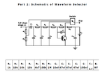
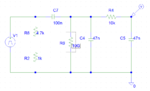
I have constructed the circuit in PSPICE schematics (please see attached) and I still find that there are floating nodes though I have connected the AGND (analog ground) component to my circuit. Kindly enlighten me on this issue.

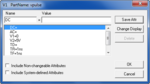
Please see attached for error message, schematic and vpulse parameters.
take note the circuit I have constructed is when second switch from the top in "ON".
I have done so because I do not know which switch I should use.
 

Attachments

  • Message.png
    Message.png
    4.2 KB · Views: 95
  • switch2.png
    switch2.png
    16.6 KB · Views: 100
  • vpulse settings.png
    vpulse settings.png
    19.9 KB · Views: 98
  • waveform selector schematic.png
    waveform selector schematic.png
    45.3 KB · Views: 110

The upper node of C4 has no dc path to ground (resp. to a voltage source).
Recommendation: Use a large-valued resistor (1E10) across the capacitor.
 

    V

    Points: 2
    Helpful Answer Positive Rating
The upper node of C4 has no dc path to ground (resp. to a voltage source).
Recommendation: Use a large-valued resistor (1E10) across the capacitor.

Thank you for your reply.
When you say across you mean parallel to capacitor C4 right? I have placed a 10 G ohm resistor across it.

I have attached the revised circuit with its output. I am unsure if this is the desired output I should get since in my lab I got something like a sine wave. Is the output I selected correct?
I have also included the schematic. The switch which I turn on now is the second switch from the top
 

Attachments

  • revised.png
    revised.png
    13.5 KB · Views: 80
  • revised_output.png
    revised_output.png
    13.1 KB · Views: 78
  • waveform selector schematic.png
    waveform selector schematic.png
    45.3 KB · Views: 141

Status
Not open for further replies.

Similar threads

Part and Inventory Search

Welcome to EDABoard.com

Sponsor

Back
Top