Continue to Site

Welcome to EDAboard.com

Welcome to our site! EDAboard.com is an international Electronics Discussion Forum focused on EDA software, circuits, schematics, books, theory, papers, asic, pld, 8051, DSP, Network, RF, Analog Design, PCB, Service Manuals... and a whole lot more! To participate you need to register. Registration is free. Click here to register now.

FIR core xilinx not working

Status
Not open for further replies.

dionysian

Junior Member level 1
Joined
Jun 12, 2010
Messages
15
Helped
6
Reputation
12
Reaction score
6
Trophy points
1,283
Location
Southern Cali
Activity points
1,420
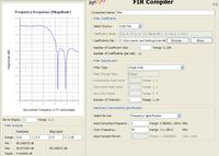
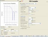
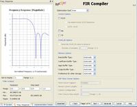
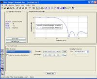
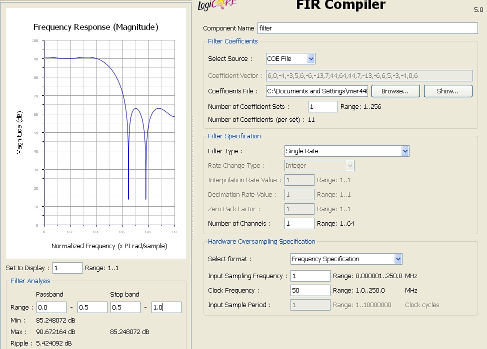
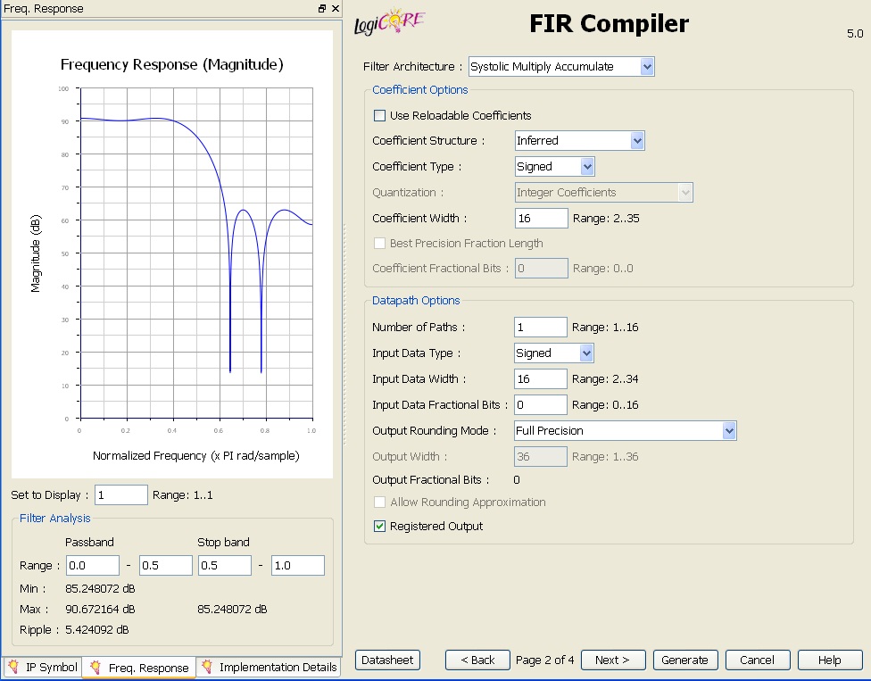
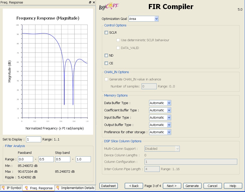
I am having a major problem getting the FIR core to work in my design. Here is what I have done so far. I have created a design which contrains a cordic which generates a sine and cosine wave and I am able to change the frequency of these wave over a wide range of frequencies. I have also created a filter using MATLAB fdatool and I made sure it was in fixed point direct form I format. I then took the coeffiecient file generated from MATLAB and Imported it into my FIR filter in my design. When It imports everything seems fine. The frequency response looks about what I would expect and I set the settings for the filter appropriately. I then simulated the filter in modelsim and now matter what frequency I put in the signal passes through unfiltered. I don’t know what to do because I am not receiving errors everything looks fine but It is simply not working. I wish I could provide more detail but there isn’t really anymore. I have attached screen shots of the modelsim output and the settings I am using for the FIR filter core. If anyone could possibly help me I would greatly appreciate it.


Thanks.
 

for the filter:
look into halfband FIR filters. they are very efficient.
look into using a DDS. this is an alternative to using a cordic.

for the problem:
make sure you have the correct signals. Its easy to forget to connect the output of a filter.
Make sure you are simulating the correct file, and recompile it to be sure.
Make sure you will get an output -- if you have an I filter and a Q filter, make sure both receive a signal.
Change the input to an impulse every N cycles. This should show you the impulse response, which will be the coefficients.
 

Thank you very much for your replay my problem was when i generated the fileter in matlab is used the wrong sampling frequecny.... for some reason i though that it wouldn't matter....
 

dionysian said:
Thank you very much for your replay my problem was when i generated the fileter in matlab is used the wrong sampling frequecny.... for some reason i though that it wouldn't matter....

So, did changing the sampling frequency with correct value solved your problem?
 

Status
Not open for further replies.

Part and Inventory Search

Welcome to EDABoard.com

Sponsor

Back
Top