Continue to Site

Welcome to EDAboard.com

Welcome to our site! EDAboard.com is an international Electronics Discussion Forum focused on EDA software, circuits, schematics, books, theory, papers, asic, pld, 8051, DSP, Network, RF, Analog Design, PCB, Service Manuals... and a whole lot more! To participate you need to register. Registration is free. Click here to register now.

Finite State Machine for signal generator

Status
Not open for further replies.

MSAKARIM

Full Member level 3
Joined
Jun 2, 2015
Messages
154
Helped
1
Reputation
2
Reaction score
4
Trophy points
1,298
Activity points
2,528
I need help to solve this problem.

Design a finite state machine capable of generating two signals, UP and DOWN, as illustrated in figure. These signals are controlled by two inputs, GO and STOP.When GO changes from ‘0’ to ‘1’, the output UP must go to ‘1’ too, but T¼10 ms later. If GO returns to ‘0’, then UP must return to ‘0’ immediately. However, the output DOWN must now go to ‘1’, again 10 ms later, returning to ‘0’ immediately if GO changes to ‘1’. If the input STOP is asserted, then both outputs must go to ‘0’ immediately and unconditionally. Assume that a 10 kHz clock is available.
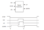
FSM.png
 

Ok - no irony - whats the problem you're having creating the state diagram??
 

The only issue I see with generating an FSM is the requirement that the output up/down has to immediately change if the signals go and stop change to the inactive state. This means you can't register those outputs but need to have either an edge or level triggered circuit to generate those outputs (asynchronous outputs) based on the go and stop signals.

Because of this condition you will have to implement this as a Mealy machine.

If you can't create a state diagram for this then you probably need to go back and review your class notes on this. Or perhaps look at some of the FSM tutorials that already exist (do a web search).
 

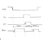
Is this try true? just a start
yeA59B2yKtJ6JX4YXK748HXQ.jpg

Code:
--
           entity Signal_generator is
           port(clk,Go,Stop:in std_logic;
            Up,Down:out std_logic); 
            end Signal_generator ;
            ---------
            architecture Signal_generator of Signal_generator is 
            type state is (state1,state2,state3);
            signal pr_state,nx_state: state;
            begin
                --------
                process(clk,stop)
                    begin
                        if (stop='1')then 
                        pr_state<= state1;
                        elsif (clk'event and clk='1') then 
                        pr_state<=nx_state;
                    end if;
                end process;
                -------
                   process(Go,pr_state)
                   begin
                   case pr_state is
                   ---1----
                   when state1 => if(go'event and go='1') then 
                    up<='1' after 10 ms;
 

Not a good start, first draw up a bubble diagram of the states and the transitions between states.

Code the FSM as a Mealy FSM (search for mealy state machine example) this should give you something that will work.

As it is you're creating some probably non-synthesizable code by making go edge triggered in a FSM state transition (can't be done). You need to keep in mind this is not a programming language it's a hardware description language so you have to describe what hardware circuits you are trying to emulate.

hardware wise up is more like this:


Code VHDL - [expand]
1
up <= '1' when (state = go_t) or (state = go) else '0';  -- up is 1 during T interval and during go high, otherwise it's 0.


Forgive any syntax mistakes (I usually use Verilog)
 
Status
Not open for further replies.

Part and Inventory Search

Welcome to EDABoard.com

Sponsor

Back
Top