Continue to Site

Welcome to EDAboard.com

Welcome to our site! EDAboard.com is an international Electronics Discussion Forum focused on EDA software, circuits, schematics, books, theory, papers, asic, pld, 8051, DSP, Network, RF, Analog Design, PCB, Service Manuals... and a whole lot more! To participate you need to register. Registration is free. Click here to register now.

Finding the Internal resistance of the following rectifier circuit

Status
Not open for further replies.

Daniel San

Newbie level 3
Newbie level 3
Joined
Dec 27, 2013
Messages
4
Helped
0
Reputation
0
Reaction score
0
Trophy points
1
Visit site
Activity points
47
Given the following circuit:

bfrNDC5.png


Find the internal resistance of the circuit, as seen when looking from Vo (voltage at the capacitor/resistance).

I've tried looking for an answer on the web, but was unable to do so. During the exercise I found:

Vm - mean output voltage
Vo - Max output voltage ( Vin - 0.7)

If anyone could point me in the right direction I'd appreciate!

Thanks.
 

Re: Find the Internal resistance of the following rectifier circuit

Rd (Resistance of diode) = Forward Voltage Drop/Current

Hence, Rd = Vf/I = 0.7/I ohms

R and C are parallel to each other.

Let Xc be the capacitive reactance.

Xc=1/2.pi.f.C ohms

Hence, Rp = R*Xc/R+Xc

Rt(Total Resistance) = Rd +Rp

Hence,

Rt = 0.7/I + R*Xc/R+Xc

Rt = 0.7 + I*R*Xc/IR + IXc

But IR = IXc (Parallel Components R and C)

Therefore the final equation is

Rt = 0.7 + I*R*Xc/2IR

Hope this helps.
 

Re: Find the Internal resistance of the following rectifier circuit

I suppose the exercise is meant to determine impedance? (Even though it says resistance.)

Moreover, is it (a) impedance during each half of the AC cycle, or (b) average impedance?

If it is A...

Then resistance is very low during the conducting part of the cycle, and very high during the other half of the cycle.

The capacitor will charge very quickly during the conducting part of the cycle. Its ohmic resistance can be assumed to be zero.

Or, if the exercise is B, to determine the average figure...


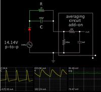
Component values were selected to produce typical behavior.

Current flows from the source only during the positive portion of the sine wave. This is just like a half-wave power supply.

By installing an averaging circuit, we find average current is .4 A. (Divide .08 mV by .2 ohm.)

The supply is 10 VAC nominal. Hence the average impedance is 10 / .4.
25 ohms.
or 1.25 * R.
The resistor value is the chief factor. Secondary influences are diode resistance and capacitor reactance.

This formula cannot be generalized to apply to all values of C and R. Using a simulation is a way to check the math.
 

Re: Find the Internal resistance of the following rectifier circuit

Given the following circuit:

bfrNDC5.png


Find the internal resistance of the circuit, as seen when looking from Vo (voltage at the capacitor/resistance).

I've tried looking for an answer on the web, but was unable to do so. During the exercise I found:

Vm - mean output voltage
Vo - Max output voltage ( Vin - 0.7)

If anyone could point me in the right direction I'd appreciate!

Thanks.

You mean which direction the charge is flowing. In one direction, the diode resistance is very high. In the opposite direction the, diode resistance is very low. The resistor itself is the same in both directions of charge flow. Now, which direction of charge flow did you have in mind?

Ratch
 

Re: Find the Internal resistance of the following rectifier circuit

It's a bit of a bastardization of terms, but one useful definition of output resistance would be (change in average output voltage) / load current.

For example, for the half-wave rectifier circuit shown, if the frequency is 50Hz and the capacitor is 10000uF, then 1A of load current will cause approx 2V pk-kpk ripple and a 1V reduction in average output voltage.

So we could say that the supply has an effective output resistance of one Ohm, since the average output voltage reduces by 1V per amp of load current.

To generalize, the effective output resistance (in Ohms) = 10000 / the capacitance (in uF).
 

Re: Find the Internal resistance of the following rectifier circuit

Averaged DC resistance would be a reasonable interpretation of the question. But an exact solution involves a non-linear differential equation and is far from easy to calculate.
 

Re: Find the Internal resistance of the following rectifier circuit

Granted. What I gave is just a thumb-**** approximation assuming ripple is a small fraction of output voltage. I find it's useful e.g. to quickly calculate roughly what size capacitor is needed to keep ripple < 10%.

edit: I'll be damned, Who would have thought "thumb-s u c k" would be censored?
 

Re: Find the Internal resistance of the following rectifier circuit

It's a bit of a bastardization of terms, but one useful definition of output resistance would be (change in average output voltage) / load current.

For example, for the half-wave rectifier circuit shown, if the frequency is 50Hz and the capacitor is 10000uF, then 1A of load current will cause approx 2V pk-kpk ripple and a 1V reduction in average output voltage.

So we could say that the supply has an effective output resistance of one Ohm, since the average output voltage reduces by 1V per amp of load current.

To generalize, the effective output resistance (in Ohms) = 10000 / the capacitance (in uF).

My thinking is that the static resistance of a nonlinear circuit cannot be expressed as a single number because its resistance depends on the direction and can be dependent on the amount of current driving it. I disregard the capacitance and inductance because they dissipate no energy like a resistor does.

Ratch

- - - Updated - - -

Averaged DC resistance would be a reasonable interpretation of the question. But an exact solution involves a non-linear differential equation and is far from easy to calculate.

If I gave you the exponential equation and even the Vf vs current plot of that equation of a forward biased diode from 0 volts to just below its max current rating, how would you give me one figure for its resistance? What would that figure mean?

Ratch
 

Re: Find the Internal resistance of the following rectifier circuit

May I add my opinion to the question in post#1 ?

At first I would ask the fellow who wants the output impedance of this non-linear circuit: How do you define the quantity you are asking for ?
 
  • Like
Reactions: FvM

    FvM

    Points: 2
    Helpful Answer Positive Rating
Re: Find the Internal resistance of the following rectifier circuit

My thinking is that the static resistance of a nonlinear circuit cannot be expressed as a single number because its resistance depends on the direction and can be dependent on the amount of current driving it. I disregard the capacitance and inductance because they dissipate no energy like a resistor does.

Of course. You get an output voltage versus load current characteristic with different differential resistance (dV/dI slope) for different load currents.
 

Re: Find the Internal resistance of the following rectifier circuit

Normally, the output resistance/impedance of an (active) circuit is measured/simulated by feeding a signal into the output and calculate the ratio voltage-to-current with correct dc biasing and ALL input excitements switched-off. This ensured that the wanted ratio does not depend on any input signal and its variations.
In the case under discussion this would mean that the diode is dead (infinite resistance).
I think, in case of a rectifier circuit, nominal AC input would be considered as part of a regular bias condition. But I completely agree with your previous post, we have to ask for a definition.
 

Status
Not open for further replies.

Part and Inventory Search

Welcome to EDABoard.com

Sponsor

Back
Top