Continue to Site

Welcome to EDAboard.com

Welcome to our site! EDAboard.com is an international Electronics Discussion Forum focused on EDA software, circuits, schematics, books, theory, papers, asic, pld, 8051, DSP, Network, RF, Analog Design, PCB, Service Manuals... and a whole lot more! To participate you need to register. Registration is free. Click here to register now.

Filter calculation for dc-ac converter

Status
Not open for further replies.

jean12

Advanced Member level 2
Joined
Aug 27, 2013
Messages
529
Helped
5
Reputation
12
Reaction score
6
Trophy points
18
www.ntigltd.com
Activity points
5,497
Hello there,can anyone help me to make calculation for dc-ac converter and determine the frequency with which I have to switch the Power MOSFET?
See the circuit herein attachment,I am repairing a dc-ac converter whith the following characteristics:

Power:750VA
Output Voltage:220V
Frequency:50Hz

That circuit in attachment is the one which were used but the controlling circuit was burnt so I want to design a new one but I thing I have to refer to the filtering circuit,

Please help on this.

Thanks.!!!
 

Attachments

  • diagram.bmp
    3.1 MB · Views: 68

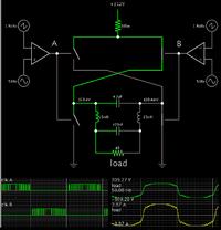
This simulation portrays my guess at what's happening.

AC square waves come from the H-bridge, then through a filter. The load sees a sinewave.


The coils have a 'choke' effect on AC going through them. The higher the carrier frequency, the less current they allow.

It's a question what frequency will cause a lot of current to go through C2 and C1.

As a guess I used 15mH for the coils, and a carrier frequency of 1.9 kHz.

C2 is exposed to large current spikes. Either 4.7 uF is too large a value, or something is wrong with my concept.
 

C2 is exposed to large current spikes. Either 4.7 uF is too large a value, or something is wrong with my concept.
Just a stupid idea. Any capacitance value connected directly to the H-bridge output is unwanted or in other words "too large".

It will cause excessive switching losses and generate interferences. A large value like 4.7 uF is likely to kill the H-bridge. RC snubbers may be O.K. to compensate for a poor circuit layout.
 

Status
Not open for further replies.

Similar threads

Part and Inventory Search

Welcome to EDABoard.com

Sponsor

Back
Top