Continue to Site

Welcome to EDAboard.com

Welcome to our site! EDAboard.com is an international Electronics Discussion Forum focused on EDA software, circuits, schematics, books, theory, papers, asic, pld, 8051, DSP, Network, RF, Analog Design, PCB, Service Manuals... and a whole lot more! To participate you need to register. Registration is free. Click here to register now.

Ferrite balun - additional winding question

Status
Not open for further replies.

ge

Full Member level 5
Joined
Jun 23, 2006
Messages
250
Helped
29
Reputation
58
Reaction score
29
Trophy points
1,308
Location
Pennsylvania, USA
Activity points
2,772
Ferrite balun

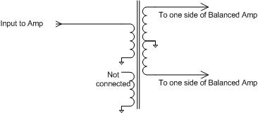
When winding transformers & baluns I sometimes see an additional winding where the additional winding is grounded on one side. Somewhere I herd that the additional winding reduces parasitic capacitance. Can anyone provide details or references?

thanks


9_1246364952.jpg
 

Re: Ferrite balun

I'm not quite sure but I think that two twisted pairs would be winded on the core. You use twisted pairs to get a transmission line transformer for higher frequency operation. This is equivalent to reducing the parasitic capacitance. I assume the unconnected winding is one of both threads of the primary that is not used because a 4:1 impedance transformation is needed.
 

Re: Ferrite balun

tnx Radiohead,

Know of any write-up on this? I've been looking through the books and found nothing.
 

Re: Ferrite balun

This approach of using an extra coupled inductor for reducing the parasitic capacitance is used not only on ferrite baluns, but also when designing planar printed baluns. In this way the SRF of the balun can be increased more than 30%.
 

Re: Ferrite balun

Tnx Vfone & Radiohead,

I can see how the capacitance to ground between the windings will increase. What capacitance decreases and how? I've started combing thru IEEE papers and still don't get it.
 

Status
Not open for further replies.

Part and Inventory Search

Welcome to EDABoard.com

Sponsor

Back
Top