Continue to Site

Welcome to EDAboard.com

Welcome to our site! EDAboard.com is an international Electronics Discussion Forum focused on EDA software, circuits, schematics, books, theory, papers, asic, pld, 8051, DSP, Network, RF, Analog Design, PCB, Service Manuals... and a whole lot more! To participate you need to register. Registration is free. Click here to register now.

feeding a horn with a patch antenna

Status
Not open for further replies.

per_lube

Advanced Member level 4
Full Member level 1
Joined
Sep 29, 2010
Messages
107
Helped
17
Reputation
34
Reaction score
17
Trophy points
1,298
Visit site
Activity points
2,120
I saw in one of the industrial position sensor (a microwave one) use a horn antenna.

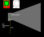
According to what I saw, the circular horn is fed with a patch antenna. (patch antenna is just connected at the small end of the circular horn)
I thought the horns can only be fed with waveguides, but now it seems there are other methods of feeding horns...

Is it possible to feed a horn with a patch antenna? what are the advantages of it?

could anyone explain it please....

cheers,
per_lube
 

I do not see the problem here, horn antenna is itself a waveguide, you just feed it with a patch.
Horn antenna can be equipped with additional machined alloy circulator to produce good TX/RX isolation

advantages: cheaper, because of smaller area of good microwave PCB. Patch antenna can be connected to schottky diode and provide self-mixing patch to directly get IF.

disadvantages: bad TX/RX isolation

p.s. I saw designs, where waveguide was feed with PCB patch, then waveguide signal comed to Lambda/4 small pin and again into another PCB. I think waveguide before horn is used for Gunn diode designs, and direct PCB patch is good for Fet DRO transistor oscillators.
 
Thanks Terminator3 for your nice explanation.

Just for information, The design I saw has two units for Tx and RX. One unit contains only Tx cct and the other one has only the RX unit.
Both units have this arrangement (Horn + Patch) for the antenna.

Will there be a loss in gain of the overall antenna when fed in this way?

cheers,
per_lube
 

That's a difficult question for me, as i do not know theory part well. Hope somebody can answer better. From my DIY experience, if horn ground is connected well and there is no gaps, i saw only gain improvement. Horn make beam narrower, so more power for transmit or receive. If there is any gaps in ground connection, there was huge noise from maybe vibration of ground connection, or low signal because of leakage.
For solving such problem there must be a good way of connecting horn to PCB:
horn-terminator.png
There can be four screws to tighten up whole construction.
I saw horns with rectangular hole with and without smoothed edges. Not sure about feeding horn with cylindrical hole.
 
per_lube , Any success with your design?
Andwhat experts think about my lame method of horn antenna feeding?
I recently read this page: **broken link removed** , it reminded me this topic. Good thing to learn.
They use lambda/4 ROD inside waveguide to feed horn antenna.

So i guess we can replace that rod by labmbda/4 microstrip without ground plane and put small lambda/4 waveguide behind it?
Can we get more gain using ROD, or ROD-like microstrip. Or it would be the same as with silly patch with a horn on it?

Thanks
 
A horn is a expanding waveguide - actually something of a controlled way of matching the impedance of the starting waveguide to that of free space.
At some stage, the wavguide needs a transition of some sort to deliver or accept power, usually into TEM coaxial. The waveguide will have an antenna structure in it. The most common, well-known, is the simple probe, which acts like a little monopole over a conducting groundplane. It radiates omnidirectional, so it is placed such that there is a back-short reflector cavity to ensure the energy efficiently gets sent toward the open end.

A patch antenna could be used as a transition, just so long as the energy launches forward down the guide. Since one can have ready-made circular polarization by using asymmetric patch, it is not too surprising that you find them in back of a horn.
 
I found something for those who interested in this topic.
Search for: patch excited horn antenna, horn antenna fed by a microstrip patch
And you will find few papers on this topic, very interesting
 
Thanks all for your nice ideas & explanations...

Actually I made a horn antenna with patch feed. I used a inset fed rectangular patch antenna.

It works very well at 12 GHz (my patch antenna works at 12 GHz and has a -10dB bandwidth of 0.3 GHz).
I use a conical horn (made out of a thin sheet of metal). Achieved 15 dBi gain with 75 mm (3'') end dia & 100 mm (4'') length horn.

Radiation pattern was nice and having a -3dB beam width of 25 deg.

Apart from the narrow band operation, I didn't see any problem with that. Actually my requirement was a narrow band antenna.

If anyone needs a narrowband high gain antenna, I think this method would be a nice option.
No need of expensive feeds for horns. Just use a simple patch antenna!
 
Actually I made a horn antenna with patch feed. I used a inset fed rectangular patch antenna.
It works very well at 12 GHz (my patch antenna works at 12 GHz and has a -10dB bandwidth of 0.3 GHz).
I use a conical horn (made out of a thin sheet of metal). Achieved 15 dBi gain with 75 mm (3'') end dia & 100 mm (4'') length horn.
Radiation pattern was nice and having a -3dB beam width of 25 deg.

Excellent! A nice result..
Since you have some knowledge radiation pattern, might it be OK to ask if the E-Plane pattern was something similar to the H-Plane?

Also, given that the horn was conical, whether your patch antenna directly provided circular polarization launched into the cone?
 
Excellent! A nice result..
Since you have some knowledge radiation pattern, might it be OK to ask if the E-Plane pattern was something similar to the H-Plane?

Also, given that the horn was conical, whether your patch antenna directly provided circular polarization launched into the cone?

yes, E-plane & H-plane are similar and looks normal.
I used linearly polarized patch antennas (inset fed rectangular microstrip patch ant's.).
Cross polarization level of the assembly (patch ant. + horn) is about 18-20 dB, from what I can remember.
I don't have the pair of antennas with me now. Otherwise I could have measure it again.

Can it be considered as linearly polarized? or is it elliptical?
could anyone shed some light please?
 
Last edited:
I think the circular horn will initially support the linear TE10 mode, in the plane it was launched in. For receiving incoming linear polarization, the horn would have to be rotated until the patch lines up with the incoming. I guess you could also have used a pyramidal horn.

Incoming circular polarized TE11 would also excite the antenna, but the patch would only receive the component in line with the patch, so that would be -3dB down.

Similar for elliptical polarized. The patch would see the linear component. Depending on the small end diameter, higher order modes like TE21 might be excited, and these might happen anyway in the wider parts of the horn.

Clearly a patch antenna can launch a wave, and adding horn boundaries around it can modify the pattern, and change the gain, and that might be it's useful feature. To get a wave going in a guide the regular way, and match it into a horn, the simple probe is good, but you may value the constructional convenience of a printed laminate instead, especially if it has on it various electronics and passive printed stuff as well.
 
Hi fiwi,

Thanks for your nice simulation result.

Is this one for a circularly polarized patch or linearly polarized patch?
I tested only the linearly polarized patch.

I'm interested to know what happens with a circularly polarized patch as well.
 

Hi fiwi,

Thanks for your nice simulation result.

Is this one for a circularly polarized patch or linearly polarized patch?
I tested only the linearly polarized patch.

I'm interested to know what happens with a circularly polarized patch as well.

hi lube!
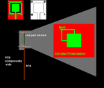
,,, for circular polarization, should another patch...!!!

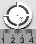
,,,so...8587_Figure7.jpg

,,,for you...horn-terminator.png
 
Last edited:
Status
Not open for further replies.

Part and Inventory Search

Welcome to EDABoard.com

Sponsor

Back
Top