cupoftea
Advanced Member level 5
Hi,
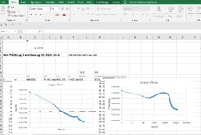
We all know that in an SMPS's, the output LC filter resonant frequency should be at least 3x more than the SMPS's crossover frequency.
Theory tells us that if it isnt then this filter will interfere with the feedback loop of the SMPS.
However,
In real life....ie shedloads of reverse engineered SMPS's......
This is never the case...........to do so would usually mean a ridiculously small inductor in the output LC filter...not to mention a ridiculously small capacitor getting used.
Not to mention that often the loads that get connected to the SMPS almost always comprise a good few 100's of uF at their input....so by the time the SMPS is powered up...the "actual", real LC output filter resonant frequency is way, way under the crossover frequency of the SMPS.
So what's behind all this?
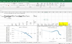