F
fourtytwo
Guest

No because two opto's are used with the leds connected in inverse parallel.Don't you need at least one extra diode anyway since the optos surely can't block mains? So rectifier would be one more......
- - - Updated - - -
Hi,
To be true I didn'd go through each word in this thread.
What I am missing: There is a requirement for "low phase shift" ...but I don't see any specification.
And I can't find the information what the signal is used for...
Without a value you may discuss a long time and never get to an end.
****
Zero cross.
I'm designing high precision phase control for the industry. And I use zero cross circuits to align the firing angle oir the SCRs.
I found out, that the "phase shift" is a minor problem for a precise regulation.
There are other, like
* timing jitter caused by overtones / distortion of the input (mains) signal
* multiple zerocross trasitions
* voltage fluctuations of mains, causing output signal fluctuations (even with precise phase)
Klaus
Hello Klaus thank you for your reply. For a specification I could try a transition <=100uS either side of zero cross in the most economical least cost manner. I have a circuit that works reasonably well BUT the power dissipation (~1.5W) is a bit of a problem on a compact circuit board with adjacent components, mostly because I laid out the PCB before I realized how low a resistance I would need to close the deadband gap.
As for the application lets just say the wider the deadband the more distortion occurs at zero cross as the resulting signals are used to drive an unfolder.
A lot of filtering and noise rejection is done in software BUT the timing accuracy of the basic signals is still important.
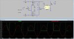
The picture (if I can load it) shows 240V grid and a software representation of zero-cross)