Continue to Site

Welcome to EDAboard.com

Welcome to our site! EDAboard.com is an international Electronics Discussion Forum focused on EDA software, circuits, schematics, books, theory, papers, asic, pld, 8051, DSP, Network, RF, Analog Design, PCB, Service Manuals... and a whole lot more! To participate you need to register. Registration is free. Click here to register now.

Explorer16 PIC24F board SPI interface write.

Status
Not open for further replies.

parthiv2eng

Member level 2
Joined
May 5, 2010
Messages
48
Helped
1
Reputation
2
Reaction score
1
Trophy points
1,288
Location
Houston
Activity points
1,572
Hello, Here's my SPI.C file. I don't get any output from _RF8 or SDO1 port. Please Help..!!

Code:
[syntax=c]#include "main.h"

volatile SPI_STORE SPI_store;

void WriteSPI1(unsigned int data_out)
{  
          SPI1BUF = data_out & 0xff;    /*  byte write  */
}

void InitSPI1()
{
	TRISF = 0x0000; // output
	SPI1CON1 = 0x0120;
  	SPI1STAT = 0x8000;

	TCSSRC = 0;// make CSSRC pin output
	CSSRC  = 1;// de-select the Serial SRC

                SPI_store.REG1 = 0xC0;	// Track ON, Mode default
	SPI_store.REG2 = 0x00;  // Filter control register
	SPI_store.REG3 = 0x11;	// 24 bit i/o I2S format
	SPI_store.REG4 = 10;	// Initial value??
	
	CSSRC = 0;// select the SRC4193
	
	WriteSPI1(1);// write Reg Address (Byte 0)
	WriteSPI1(0);// write Dummy (Byte 1)
	WriteSPI1(SPI_store.REG1);// write Reg 1 (Byte 2)
	WriteSPI1(SPI_store.REG2);// write Reg 2 (Byte 3) Auto Address increament
	WriteSPI1(SPI_store.REG3);// write Reg 3 (Byte 4) Auto Address increament
	WriteSPI1(SPI_store.REG4);// write Reg 4 (Byte 5) Auto Address increament
	    
	CSSRC = 1;// deselect to complete the buffer
}
[/syntax]
 

I cannot check at the moment but there is something different about SPI1 on the Explorer 16. Check the schematics in the documentation. There is some logic allowing the input & output to be reversed, I seem to remember. You need to set another port bit to make it work the right way round (or used SPI2).

Keith
 

I don't see any peripheral mapping in the code, assigning pins to SPI functions I think is a requirement of the PIC24, in the datasheet under remappable peripherals there is more info,
I have to use this (self commenting!) Add the header
Code:
"#include <pps.h>"
Code:
	// Allow Change to mapped pins.... Unlock sequence...
 		CloseSPI1(); 	
		PPSUnLock;

 	PPSOutput(PPS_RP5, PPS_SDO1);
	PPSOutput(PPS_RP6, PPS_SCK1OUT); 
	PPSInput (PPS_SDI1, PPS_RP4);        
		PPSLock;
Cool, XD
NEAL
 
Last edited:

I cannot check at the moment but there is something different about SPI1 on the Explorer 16. Check the schematics in the documentation. There is some logic allowing the input & output to be reversed, I seem to remember. You need to set another port bit to make it work the right way round (or used SPI2).

Keith

Thank you Keith. But even MPLAB logic analyzer won't show me any output. I will try SPI2 and keep post later.

---------- Post added at 02:20 ---------- Previous post was at 02:09 ----------

I don't see any peripheral mapping in the code, assigning pins to SPI functions I think is a requirement of the PIC24, in the datasheet under remappable peripherals there is more info,
I have to use this (self commenting!) Add the header
Code:
"#include <pps.h>"
Code:
	// Allow Change to mapped pins.... Unlock sequence...
 		CloseSPI1(); 	
		PPSUnLock;

 	PPSOutput(PPS_RP5, PPS_SDO1);
	PPSOutput(PPS_RP6, PPS_SCK1OUT); 
	PPSInput (PPS_SDI1, PPS_RP4);        
		PPSLock;
Cool, XD
NEAL

Thanks Neal,

Are you talking about PIC24F_Peripheral.h? I don't understand this "[/code]
Code:
	// Allow Change to mapped pins.... Unlock sequence...
 		CloseSPI1(); 	
		PPSUnLock;

 	PPSOutput(PPS_RP5, PPS_SDO1);
	PPSOutput(PPS_RP6, PPS_SCK1OUT); 
	PPSInput (PPS_SDI1, PPS_RP4);        
		PPSLock;
can you elaborate?
 

The pin-mapping libraries are in pps.h, #include <pps.h>" is the reference....

// Allow Change to mapped pins.... Unlock sequence...
CloseSPI1();
PPSUnLock;

PPSOutput(PPS_RP5, PPS_SDO1); // ASSIGNS RP5 to SDO1 (output pin)
PPSOutput(PPS_RP6, PPS_SCK1OUT); // ASSIGNS RP6 to SCK1 (output pin)
PPSInput (PPS_SDI1, PPS_RP4); // set pin RP4 to be an input, SDI1
PPSLock; // Relock the mappings to prevent accidental changes

Cool :)
NEAL
 

The PIC24FJ128GA010 (supplied with the Explorer 16) doesn't have PPS, I think.

If you look at the limitations of the MPLAB simulator for the PIC24 the SPI is not listed as a supported peripheral. If you have the Explorer 16 I would use that for debugging.

SPI1 is routed through U6 on the Explorer PCB and so you need to control RB12 to get the input & output the correct way round. SPI2 doesn't have that problem.

Keith
 
Last edited:
The PIC24FJ256GP610 (supplied with the Explorer 16) doesn't have PPS, I think.

If you look at the limitations of the MPLAB simulator for the PIC24 the SPI is not listed as a supported peripheral. If you have the Explorer 16 I would use that for debugging.

SPI1 is routed through U6 on the Explorer PCB and so you need to control RB12 to get the input & output the correct way round. SPI2 doesn't have that problem.

You are right Keith. It doesn't require pps. The book "learning to Fly the PIC24" didn't mention anything about pps while working with pic24 SPI module. But I couldn't figure out why it's not working. FYI IN my application, slave IC don't have SPI out. It means I am only doing one way communication.


No problem. The Microchip processors are incredibly confusing at times. Some PCI24F ones have PPS, some don't. I have mostly used the PIC24H and they don't have PPS (at least the ones I have used don't). Simple migrations to processors which they say are compatible often aren't as simple as you would like (eg PIC24H to PIC24E or PIC32).

Keith.
 
I do like PPS immensely, the 24FJ32Ga002 was my 1st attempt at PIC24's (controlling HTC1632s), but I found the 24FJ64GA102 was better for me as it has the onboard RTC timer osc... I'd *assumed* everything PIC24 was the same as the limited datasheets I'd checked, "assumption" being the mother of all **** (screw) ups! The MicroChip ('s own) forum claims that the PIC24FJxxxga00n hasn't PPS, and the FJxxxGA1nn has pps, but it's not that simple it seems, but fun finding out...

I was making an explorerboard-copy (on veroboard!) for the MRF24J rf modules, and had to recode the code to map the pins... If I'd realised I'd have stuck with the fixed to save a bit of effort, but no problems....

Appologies again, thanks for "discussing" me right, I always *appreciate* steering :)

:-D indeed, always fun (I hope!)
NEAL
 

I have mostly used the PIC24H and now have quite a collection of the plug in modules that come with the Explorer 16 if you need any spares! Even if I could use the PIC24FJ it is easier to stick with the same processor now as I know I can reuse code.

Keith
 

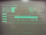
20120601_101635.jpg

Here..I got my SPI out using spimpol files from microchip. Thank you guys.

Do anyone tell me how to read this SPI code?

In Image
B0- chip select
B1- SPI clk
B2- SPI out

I am sending 5 bytes. Could you explain this image?
 

That doesn't look right. Assuming you are in 8 bit mode you should get 8 clock cycles (evenly spaced). Try just sending one byte first so it is easier to work out what is happening.

Keith.
 

That doesn't look right. Assuming you are in 8 bit mode you should get 8 clock cycles (evenly spaced). Try just sending one byte first so it is easier to work out what is happening.

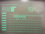
20120601_112832.jpg

Here's the one Byte data. It really seems like something wrong.
 

It seems very slow. I am not familiar with your logic analyser settings but what does the 200us/clock mean? Is that the logic analyser sample rate?

Keith.
 

It's very old HP 1630G logic analyzer. Yeah 200 us/clock is sample period.
 

Depending on your SPI clock rate, I think you need to sample the waveform quicker than every 200us with the logic analyser, unless I am misunderstanding what that 200us is (it seems awfully slow for a sample rate).

Keith
 

Depending on your SPI clock rate, I think you need to sample the waveform quicker than every 200us with the logic analyser, unless I am misunderstanding what that 200us is (it seems awfully slow for a sample rate).

Keith

I can go lowest sampling rate 20us/clk

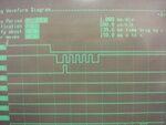
Here's the output. What do you think? I have tried to use all diff oscillator on board. Still same.

20120601_141256.jpg
 

That looks better. I think you may not be getting the best out of the logic analyser - I looked up the specification and it can sample at 25MHz.

Keith
 

Status
Not open for further replies.

Similar threads

Part and Inventory Search

Welcome to EDABoard.com

Sponsor

Back
Top