Continue to Site

Welcome to EDAboard.com

Welcome to our site! EDAboard.com is an international Electronics Discussion Forum focused on EDA software, circuits, schematics, books, theory, papers, asic, pld, 8051, DSP, Network, RF, Analog Design, PCB, Service Manuals... and a whole lot more! To participate you need to register. Registration is free. Click here to register now.

Explanation of a PWM Code

Status
Not open for further replies.

Help

Advanced Member level 2
Joined
Feb 15, 2005
Messages
617
Helped
7
Reputation
14
Reaction score
3
Trophy points
1,298
Activity points
7,065
Hi,

Anyone can help me to explain the code?

Code:
void PWM_3_Set_050(void)
   {
   T2CON &= 0xFD;   // Clear *only* C /T2 bit
   T2MOD |= 0x02;   // Set T2OE bit  (omit in basic 8052 clone)
  
   // Set at lowest frequency (~45Hz with 12MHz xtal)
   // - adjust as required (see PRM HARDWARE)
   TL2     = 0x00;   // Timer 2 low byte
   TH2     = 0x00;   // Timer 2 high byte
   RCAP2L  = 0x00;   // Timer 2 reload capture register, low byte
   RCAP2H  = 0x00;   // Timer 2 reload capture register, high byte

   ET2   = 0; // No interrupt.

   TR2   = 1; // Start timer 2
   }

How does it work? What's the program doing? How can it generate the frequency at P1^0? I try to changed it to P2^1 but still generated at P1^0..why?

Thank You.
 

pwm servomotor 4mhz

This routines initiliaze the pwm registers of MCU.

You must lean the hardware pwm unit of MCU, If you want to learn what does this codes.
 

Re: PWM Code Explanation

It used Timer2 in Clock-Out Mode, not PWM unit in MCU. (standard 8052 has not this feature)
The T2OE & TR2 must be set to 1, the C/T2 has to be 0 for P1.0 (T2) as clock out.
its frequency = osc / ( 4 * (65536 - RCAP2) )
For more details, please refer to Intel's MCS(R) 51 Microcontroller Family User's Manual
BTW, its duty cycle is always 50%.
 

    Help

    Points: 2
    Helpful Answer Positive Rating
Re: PWM Code Explanation

Hi,

Osc Freq. = 11.059Mhz

Clock-Out Freq. (Theoretical) = (Osc Freq.) / (4*65536) = 42.1867Hz

Clock-Out Freq. (Practical) = 1 / 23.7mSec = 42.1941Hz

am i rite?

So, the clock-out freq. depends on the osc freq. If i'm using 11.059MHz then i only can get 42.19Hz clock generator, rite?
 

Re: PWM Code Explanation

Help said:
Osc Freq. = 11.059Mhz
Clock-Out Freq. (Theoretical) = (Osc Freq.) / (4*65536) = 42.1867Hz
Clock-Out Freq. (Practical) = 1 / 23.7mSec = 42.1941Hz
am i rite?
So, the clock-out freq. depends on the osc freq. If i'm using 11.059MHz then i only can get 42.19Hz clock generator, rite?
You can get 42.1867Hz ~ 2.7648MHz which depends on the osc freq. and value of RCAP2 (H,L).
 

Re: PWM Code Explanation

Hi,

May i know what's the alternate functions for P1.0? from the AT89C52 datasheet, there say "....has two alternate function. It can be programmed to input the external clock for Timer/Counter 2 or to output a 50% duty cycle clock...".
What does it mean? What's the 2nd function is it and how it works?

Thank You.
 

Re: PWM Code Explanation

..... to output a 50% duty cycle clock...".
What does it mean? What's the 2nd function is it and how it works?

Its mean : you can output pre program frequency clock output on T2 pin (=P1.0)

The code at your first post do that, it generate 45 Hz (12 MHz Xtal freq) clock on T2

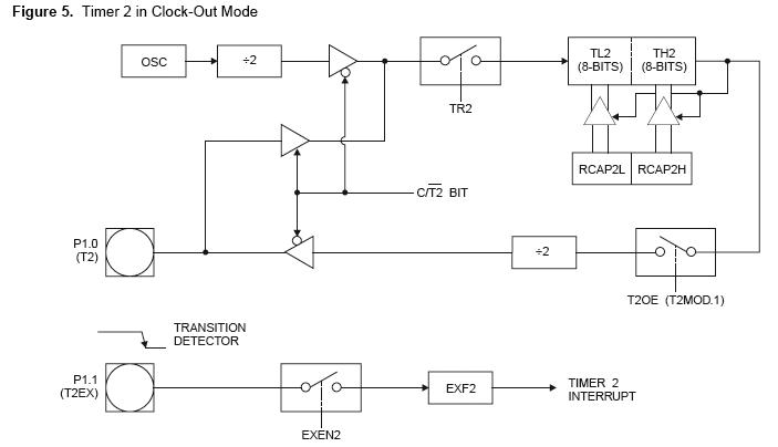
Please take a look at this diagram:

61_1165894905.gif
 

Re: PWM Code Explanation

Hi,

How bout "input the external clock for Timer/Counter 2"? How to do the setting on the code and how can i play on it?

Thank You.
 

Re: PWM Code Explanation

Programmable Clock Out
A 50% duty cycle clock can be programmed to come out on P1.0, as shown in Figure 5. This pin, besides being a regular I/O pin, has two alternate functions. It can be programmed to input the external clock for Timer/Counter 2 or to output a 50% duty cycle clock ranging from 61 Hz to 4 MHz at a 16 MHz operating frequency.

To configure the Timer/Counter 2 as a clock generator, bit C/T2 (T2CON.1) must be cleared and bit T2OE (T2MOD.1) must be set. Bit TR2 (T2CON.2) starts and stops the timer. The clock-out frequency depends on the oscillator frequency and the reload value of Timer 2 capture registers (RCAP2H, RCAP2L), as shown in the following equation.
70_1165895673.gif

In the clock-out mode, Timer 2 roll-overs will not generate an interrupt. This behavior is similar to when Timer 2 is used as a baud-rate generator. It is possible to use Timer 2 as a baud-rate generator and a clock generator simultaneously. Note, however, that the baud-rate and clock-out frequencies cannot be determined independently from one another since they both use RCAP2H and RCAP2L.
 

Re: PWM Code Explanation

Hi,

Thank for you info. This all info we can get from datasheet. I go through this info already but not really understood.

From my first post the code setting...
Code:
   T2CON &= 0xFD;   // Clear *only* C /T2 bit
   T2MOD |= 0x02;   // Set T2OE bit  (omit in basic 8052 clone)

Is it the Timer/Counter 2 and the clock-out setting is the same? How does it work actually? Please can you make me clear on it? again... How to do the setting on the code and how can i play on it?

Thank You.
 

Re: PWM Code Explanation

You use Timer 2 in Clock-Out mode when two SFR bits are configured as follows:
C/T2 = 0
T2OE = 1
The first condition can be done by writing FDh to T2CON, the second by writing 02h to T2MOD .

If you want to "PLAY" with frequency on pin P1.0 "PLAY" with these two reload bytes:
RCAP2H and RCAP2L ..

Regards,
IanP
 

Re: PWM Code Explanation

Your Code generate clock on T2 pin only, no other purpose!

Is it the Timer/Counter 2 and the clock-out setting is the same? How it work actually?
No, they are different, refer to Figure 1 on datasheet for Counter 2 with external Clock Source (injected to T2 pin), and figure 5 is Timer2 as clock generator configuration.

How to do the setting on the code and how can i play on it?
What do you want to do?
Counter 2 with external Clock Source
or
Clock Generator?


Do you have PATTERNS FOR TIME-TRIGGERED EMBEDDED SYSTEMS by Michael J. Pont , or the CD of that book?
 

Re: PWM Code Explanation

Hi,

I think we already discuss the Clock-Generator(ClockOut) in our previous post..

So, how bout Counter 2 with external Clock Source? Please can you guide?

Thank You.

I dont have this book..but i got the sample codes for this book also downloaded from here...
 

Re: PWM Code Explanation

Setup Counter 2 with external Clock Source :

Set Timer2 operate on 16-Bit Auto-Reload or 16-Bit Capture mode (Tabel 3)
Clear T2OE = 0
Set C/T2 = 1 (Figure 1)
Set TR2 = 1 (start timer)
 

Re: PWM Code Explanation

budhy said:
Setup Counter 2 with external Clock Source :

Set Timer2 operate on 16-Bit Auto-Reload or 16-Bit Capture mode (Tabel 3)
Clear T2OE = 0
Set C/T2 = 1 (Figure 1)
Set TR2 = 1 (start timer)

Hi,

How to do the setting for Timer2 operate on 16-Bit Auto-Reload or 16-Bit Capture mode ?

Actually how it work? how to control the T2 pin signal? I only know to control the T2EX for T2 Interrupt.

Code:
void CounterII(void)
   {

   T2CON &= 0xFF;   // Set C bit
   T2MOD |= 0x00;   // Clear T2OE bit  
 
   TR2   = 0; // The timer should be turned off(clear TR2) before accessing the T2 or RCAP2 registers.


   TL2     = 0xf0;   // Timer 2 low byte
   TH2     = 0xff;   // Timer 2 high byte
   RCAP2L  = 0xf0;   // Timer 2 reload capture register, low byte
   RCAP2H  = 0xff;   // Timer 2 reload capture register, high byte


   ET2   = 1; // T2 interrupt.
   EA    = 1; // Globally enable interrupts

   EXEN2 = 1;
   RCLK  = 1;

   TR2   = 1; // Start timer 2

   }

Please help me to check my code!

Thank You.
 

Re: PWM Code Explanation

I am having similar problem with clock out mode, which i just want to check. I did the coding in Keil uvision3 and upon running the program the P1.0 is not toggling .I am also attaching the code.
 

Status
Not open for further replies.

Similar threads

Part and Inventory Search

Welcome to EDABoard.com

Sponsor

Back
Top