Continue to Site

Welcome to EDAboard.com

Welcome to our site! EDAboard.com is an international Electronics Discussion Forum focused on EDA software, circuits, schematics, books, theory, papers, asic, pld, 8051, DSP, Network, RF, Analog Design, PCB, Service Manuals... and a whole lot more! To participate you need to register. Registration is free. Click here to register now.

[SOLVED] Explain Purpose of Capacitor in this Circuit

Status
Not open for further replies.

hshah8970

Full Member level 2
Joined
Sep 17, 2011
Messages
144
Helped
18
Reputation
36
Reaction score
18
Trophy points
1,308
Activity points
2,385
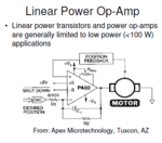
Hello! This is a circuit for a motor being driven by an opamp. I do not understand the purpose of the C1 in there. Is it some sort of external compensation for the inductive load (motor) ?

Also, if you can, please tell me what a linear power opamp is? I mean what would a non-linear power opamp mean?
123.png
 

Dear hshah
Hi
It can has two effect . first one is a compensation capacitor . and the other one is to prevent from damages of opamp instead of high voltage spikes .
By the way , is that kind of DC motor ?
Best Wishes
Goldsmith
 
thanks for replying. and yes, it's a dc motor.
 

So , if it is DC motor , it will create high value of spikes , and as you probably know , each capacitor will be short circuit in transient time . so , it won't allow that spikes , be across the opamp ! and as i told it's other duty can be as a compensation network .
Best Wishes
Goldsmith
 
Hello! This is a circuit for a motor being driven by an opamp. I do not understand the purpose of the C1 in there. Is it some sort of external compensation for the inductive load (motor) ?
Also, if you can, please tell me what a linear power opamp is? I mean what would a non-linear power opamp mean?
View attachment 75839

hshah8970,

your circuit resembles a position control system. For stabilization purposes - due to the transfer characteristics of the dc motor - a controller is necessary.
The capacitor in the negative feedback path acts as a PI controller that stabilizes the loop. That is the main purpose of the capacitor.
 
Wow, that's one beefy op-amp!

So , if it is DC motor , it will create high value of spikes , and as you probably know , each capacitor will be short circuit in transient time . so , it won't allow that spikes , be across the opamp !

That capacitor certainly isn't for absorbing current spikes, since any current spikes through it will be fed directly to the op-amp's inverting input... which is high impedance. The device does have internal diodes at its outputs to protect it from flyback events, just in case the active feedback isn't fast enough to catch a spike.

and as i told it's other duty can be as a compensation network .

Think this is on the right track. That op-amp provides pins for adding a frequency compensation cap though. I think the primary purposes for that capacitor are:
1.) Low-pass filter the DAC output, which is prone to be somewhat spiky.
2.) Output voltage feed-forward: if the motor suddenly draws more current (for example, its speed reduced to zero), this would load down the op-amp's output (due to its non-zero output impedance) and the op-amp would adjust to the change. The capacitor would feed the high frequency information unattenuated to the inverting input, therefore speeding up its response to this disturbance.

Another way of saying (2) is that the feedback capacitor would increase its loop gain at high frequencies, and therefore reduce its high frequency closed-loop output impedance.

I do not think that you need any special compensation specifically because you're driving an inductive load though; the output impedance of the op-amp is inductive, and paralleling the two should pose no stability problems.

As for your second question... It's somewhat of a misnomer to call it "linear," but that's the de-facto standard way of describing amplifiers and power regulators which adjust their output voltage by dissipating power in lossy devices. This op-amp is unusual in that it delivers hundreds of watts through lossy elements, rather than through a more efficient class-D amplifier. This is the same dichotomy that's drawn between "linear" regulators and switch-mode power supplies. While SMPS's are much more efficient than linear regulators, they also produce more high frequency noise and have limited bandwidth.
 
The capacitor in the negative feedback path acts as a PI controller that stabilizes the loop. That is the main purpose of the capacitor.
PI controller is the most likely explanation. It would be achieved if the pole frequency set by R2C1 is located below the controller closed loop bandwidth. In this case, the controller has a P gain of unity. A controller P part is required for stability with the integral acting control system.

If the pole frequency lays beyond loop bandwidth, C1 is just a high frequency filter of a P controller.
 
is that the feedback capacitor would increase its loop gain at high frequencies
Hi ZekeR
I'm disagree about this , because at high frequencies the impedance of capacitor will become low . and thus the feed back resistor will become short circuit . thus , gain become low .

and another thing to the author of thread : why not PWM method ? it is pretty stable and flexible and with lowest dissipation .
Best Regards
Goldsmith
 
As a trivial result of feedback circuit theory, increasing the feedback factor will reduce the close loop output impedance of a (stable) loop with voltage controlled feedback. But in the present circuit it'a at best a side effect. I don't see that it has a worth on it's own in a position control loop.
 
Quote ZekeR: I do not think that you need any special compensation specifically because you're driving an inductive load though; the output impedance of the op-amp is inductive, and paralleling the two should pose no stability problems.

The character of the load (resistive, inductive,...) is of less importance.
You have a closed loop control system and, therefore, the transfer function of the "plant" (that is in your case the dc motor) matters primarily.
Because I think that you have no detailed information about this transfer function you cann assume the following:

The transfer function of the dc motor with respect to the output angle (that means: not to the angular velocity) can be approximated by a I-T2 response (integrating function with two first-order delay elements).
These transfer properties require a separate controller (preferrably with PD-T1 characteristics) - however, if speed is not important, an additional PT1 element can also stabilize the loop.
 
The character of the load (resistive, inductive,...) is of less importance.
The circuit has two feedback loops, and there is a principle possibility that the "inner" feedback loop (OP output to Vin-) becomes unstable. In this regard, the load impedance matters, a capacitive load can bring up instability in a frequency range above the outer loop's bandwidth. But it's not the case for the present circuit.
 
I'm disagree about this , because at high frequencies the impedance of capacitor will become low . and thus the feed back resistor will become short circuit . thus , gain become low .

The "loop gain" is not the same as the "gain." Loop gain is defined as the gain that a signal would see if you broke the feedback loop open, injected a tiny signal into it, and saw how big it was once it propagated back around. In an op-amp amplifier, the loop gain would be a*beta, where "a" is the op-amp's open-loop gain and beta is the feedback divider ratio. At low frequencies the feedback divider attenuates the signal to R1/(R1+R2), but at high frequencies the capacitor becomes a short and the feedback division ratio grows to unity (thus, higher loop gain).

I'm not particularly familiar with motor position control, so I can learn something here. Please offer corrections where I'm wrong. =)

For a DC motor, when you apply a DC voltage, it causes the current to ramp up, causing the torque to increase, causing acceleration, and causing increased velocity... the velocity then stabilizes when the back-emf is equal to the input voltage minus the voltage across any DCR (due to the current required to overcome whatever resistive torque there is). Thus, I would think that an "unloaded" DC motor should have an integrating (single-pole) response from input voltage to output position, with two additional high frequency poles (voltage-to-current integral, and current/torque/acceleration-to-velocity integral). Then, if you load the motor with a mass, its back-torque would decrease the "torque-to-acceleration" function, bringing the "torque-to-velocity" pole lower in frequency. And if you load the motor with a friction load, the voltage-to-velocity (DC) transfer function would decrease in magnitude.

Optimal control would I think be PD control (the PD zero should ideally move around to compensate for the moving torque-to-velocity pole). That would require you knowing exactly what the motor's load is, in order to place the zero at the right spot.

The transfer function of this circuit, however, from noninverting input to its output is that of a lag compensator (not a PD compensator). It's not as optimal as a PD would be, but it still works (as long as your loop gain crossover happens beyond the lag compensator's zero and before the torque-to-velocity pole). In this way, the high frequency pole introduced by the load's mass is outside of the control bandwidth, but high loop gain within the bandwidth is maintained. (It can still be made unstable by heavy friction loads, however).

These transfer properties require a separate controller (preferrably with PD-T1 characteristics) - however, if speed is not important, an additional PT1 element can also stabilize the loop.

Can you explain how introducing a T1 delay element would help stabilize it?
 
Can you explain how introducing a T1 delay element would help stabilize it?

Hi ZekeR, it was simply a typing error. Sorry. As you can see in my posting#5 I spoke about a PI control mechanism which is established using the feedback C.
However, I completely agree with your explanations - in particular with the role of a PD-T1 controller, which can ensure a good step response. The mentioned PI characteristic also is able to stabilize the loop (if necessary!) - however with the consequence of a step response (rise time) that in many cases is not acceptable.
 
Thanks to all who responded. You've been very helpful. =)
 

Status
Not open for further replies.

Similar threads

Part and Inventory Search

Welcome to EDABoard.com

Sponsor

Back
Top