Continue to Site

Welcome to EDAboard.com

Welcome to our site! EDAboard.com is an international Electronics Discussion Forum focused on EDA software, circuits, schematics, books, theory, papers, asic, pld, 8051, DSP, Network, RF, Analog Design, PCB, Service Manuals... and a whole lot more! To participate you need to register. Registration is free. Click here to register now.

Experiement on Peltier Thermoelectric Cooler Module Behaviour

Status
Not open for further replies.

eyeow

Junior Member level 1
Joined
Jan 13, 2007
Messages
18
Helped
0
Reputation
0
Reaction score
0
Trophy points
1,281
Activity points
1,494
This thermoelectric module for cooling system is new for me. I conducted an experiment on Peltier Thermoelectric Module. I want to test how it behaves when I provide certain level of voltage and what would be the current looks like and calculate the power used before designing suitable circuit to control it.

Peltier Thermoelectric Module with max rating: 100W, 20V, 8.5A, deltaT 71DegC
https://uk.rs-online.com/web/p/peltier-modules/6935107/

Test Setup: As shown in the picture. Cold side of Peltier faced upwards exposing to ambient. Hot side faced downwards and fan+heat sink was used to dissipate the heat from there.
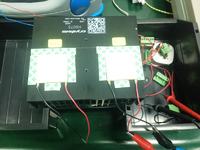
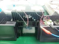

DC power supply is used to generate DC voltages 12V, 16,V and 18V to Peltier and to measure the current.

Measurement Results:

At 12V, I = 3.54A, P=42.28W
At 16V, I = 4.1A, P=65.6W
At 18V, I=4.5A, P= 81W
At 20V, I= 4.9A, P=98W

Observation:
1. When voltage increases, the current also increases. Thus the calculated power is higher.
2. When first turn on the DC power supply, eg. at 12V, the current reading at first is around 4.1A then gradually drops to 3.54A after 1 minute, and it keeps on decreasing slowly as well. Same observation happened at other voltages.
3. When I touch at the cold side, the current increases. Thus I think that more current is consumed to cool down the heat (from my finger)
4. Eventually one of the thermoelectric modules broken down, found it was open, high impedance. But the last reading was 12V and approx 3.3A. The cold side has turned hot when the moment current reading became 0A.

Questions:
Q1: Why the measured current is higher when the voltage increases? Assume the ambient is about the same, so the power used to cool down the ambient heat should be the same, right?

Q2. I didn't not exceed the max voltage 20V, and the current measured was 3.3A still far below 8.5A. What makes the thermoelectric module broken? Is it because I must always put hot object at cold side to keep this module working?

Q3. Is this how the thermoelectric module behaves? My application is to use this module to cool down water tank. So when the water tank is hot, then only I turn on the PWM to drive the thermoeletric module?

Hope to get some answer to help me understand more on its behavior. Thanks.
 

Q2. I didn't not exceed the max voltage 20V, and the current measured was 3.3A still far below 8.5A. What makes the thermoelectric module broken? Is it because I must always put hot object at cold side to keep this module working?
I think it's not a good way to make tests with that cell, because the expected usage is with a 'heatsink' at both sides, hot and cool; otherwise hot side overheats due the accumulated heating without dissipate. Once you power up the cell with the rated current, a thin ice film will be quickly produced at its surface (taken from air humidity), which tend to isolate it thermally, changing the result from the normal operation.
 
  • Like
Reactions: eyeow

    eyeow

    Points: 2
    Helpful Answer Positive Rating
Did you measured the temperature on both sides ? At start, both temperatures are equally (on the one faced up and on the bottom one). The more power you give to the Peltier, the more difference in temperature you will have. The one facing up at ambient temperature will remain aprox the same, at ambient temperature meanwhile the other one will continuously decrease.
I have done a practice this year at the university called "Continuous control of a Peltier Cell" but for my shame, I did not understand how all that work together because of my low electronics level, I did not see how the (electrical) connections were made and with the acquisition board, which channel correspond to what thing...

If you are able to understand Spanish, I could give you the whole process and connections and explanation (my practice HandBook) in which it is explained from the very basics to the data acquisition and whole software/hardware used.

This is our peltier cell.


Here is a very little explanation in english about our cell **broken link removed**
My teacher really liked the Peltier Cell and done a great work but it is a pity because me and other classmates were not very excited because we did not quite understand its functionality because of those electronic boards and process...
 
Last edited by a moderator:
  • Like
Reactions: eyeow

    eyeow

    Points: 2
    Helpful Answer Positive Rating
A peltier element acts like a resistor in first order. In the second order, the resistance has a positive temperature coefficient and there's also a small thermoelectric voltage generated by the temperature difference between both sides.

According to this characteristic, the current consumption is only slightly dependent on the hot and cold side temperature, which should answer your first question.

Peltier elements will be mostly damaged by exceeding the rated maximum temperature. I see that you are using a large heatsink, apparently with a fan. How did you attach the hot side to the heat sink, did you use thermal grease.

If the peltier element is actually ET-161-12-08-E, the measured I and V numbers suggest that the hot side is becoming much too hot at higher currents. This would also explain element damage.

If you have a limited heatsink, you'll notice that the cold temperature will reach a minimum and rise again when increasing the current. It's useless to go beyond this optimal operation point.
 
  • Like
Reactions: eyeow

    eyeow

    Points: 2
    Helpful Answer Positive Rating
If you have a limited heatsink, you'll notice that the cold temperature will reach a minimum and rise again when increasing the current. It's useless to go beyond this optimal operation point.
FvM has nailed it.

There are a few basic limits you need to keep in mind.
If the hot side gets too hot, the device will definitely die open circuit.
Too high a current will destroy it as well.

The other difficulty is these Peltier cells conduct a LOT of heat from the hot side back to the cold side within the device. So differential temperature is very limited if you expect to get good efficiency.

The specification sheet is an optimists wet dream.
Yes it might manage 71 degrees differential temperature if the hot side is water cooled and held at a very low temperature, and the cold side is perfectly insulated from the outside world with zero additional added heat load. And not too much power is applied.

The maximum ratings are exactly that, figures which if exceeded will destroy the device.

Do not expect to drive it to 100 watts input power input and expect to see 71 degrees temperature difference, it will never happen.

Its a few years since I did all this myself, but as I remember, for a 100 watt device, the most efficient operating point might be around 10 watts input power, maybe a bit less, and no more.

It might shift about 3 watts of heat from the cold side, and dissipate 13 watts from the hot side. Peak efficiency maybe 30% ( 3 watts of heat shifted for 10 watts of input power) which is as good as it gets.

You might get that at about a 10 to 15 degree temperature differential.
Higher temperature differential, or more input power will seriously reduce efficiency.
 
The specification sheet is an optimists wet dream

Another condition which deteriorates the cell is the fact that the heat is not uniformly carried along its surface, but exists punctual regions having a temperature rise above the average. Some manufacturers of household cooling products perform a screening of these cells based on the thermal imaging to detect gradients which could damage it over time. Throwing away these parts is less expensive than the amount of money spent on manufacturing warranty, not accounting yet the brand macule.
 

Peltier elements will be mostly damaged by exceeding the rated maximum temperature. I see that you are using a large heatsink, apparently with a fan. How did you attach the hot side to the heat sink, did you use thermal grease.

If the peltier element is actually ET-161-12-08-E, the measured I and V numbers suggest that the hot side is becoming much too hot at higher currents. This would also explain element damage.

If you have a limited heatsink, you'll notice that the cold temperature will reach a minimum and rise again when increasing the current. It's useless to go beyond this optimal operation point.


Nope i didn't use any thermal paste for this experiment. was thinking just a quick setup for quick measurement.

So in order to protect the peltier, i shall not exceed the delta temp of both sides as stated 71 deg C with better heat dissipation capability at its hot side, right?

ok good point to figure out the optimal operation point by looking at the cold temp side...

- - - Updated - - -

If the hot side gets too hot, the device will definitely die open circuit.
Too high a current will destroy it as well.

Do not expect to drive it to 100 watts input power input and expect to see 71 degrees temperature difference, it will never happen.

You might get that at about a 10 to 15 degree temperature differential.
Higher temperature differential, or more input power will seriously reduce efficiency.

Noted on that. I agree on the expectation of its specs as well.

i did a setup at my system with data logger on its hot & cold side. the measured Vrms = 15V, measured Irms = 3.6A, power = 54W. Differential temp of both sides approx around 40 deg C.

I started to notice the hot side is not ramping down fast enough, could be due to fan n heatsink cooling not good enough?
 

in fact this peltier is not cheap as well.
 

You might get that at about a 10 to 15 degree temperature differential.
Higher temperature differential, or more input power will seriously reduce efficiency.

This is usually treated in thermodynamics as a Carnot Engine running in reverse. This is basically a refrigerator. Energy is supplied and heat is pumped from a lower temperature to a higher temperature (just like a common refrigerator).

In thermodynamics, heat cannot be fully converted into work but the reverse does not apply. If the temperature differential is small, the supplied energy can be used to pump a lot of heat (I mean with high efficiency).

Common Peltier devices are basically semiconductor based and they produce considerable Joule heat and that reduces efficiency.
 

here is the temp records:


Notice that although its cooling like mad producing a high temperature differential, the cold side is still well above room temperature.
Its not really cooling at all unless you can pull the cold side down lower than room temperature.

When the power is shut off, the cold side temperature falls to a lower temperature than when its supposed to be cooling. Its not really doing any cooling at all.

You need a much bigger heat sink to get the hot side down closer to room temperature.

And try it at much lower power levels than 56 watts,
I think you will then start to see the cold side gets colder than room temperature, which is what this is really supposed to do.

If you can get the cold side down to zero Celsius and see some ice form, then you can say you have really made a cooler.
And that will not be easy.
 

Notice that although its cooling like mad producing a high temperature differential, the cold side is still well above room temperature.

Something is really strange here. It is heating up the hot side but not cooling the cold side. 50W of input power will all appear at the hot side, true, but is the device really working well?

I will call it "cooling" only when the cold side goes below the room temperature. Perhaps it cannot handle 50W, one must start with a lower power level.

Something is not as expected.
 

Its exactly what happens if you feed far too much power into it.

The efficiency drops to zero, then well below zero as more heat conducts through to the cold side, than the cell can pump from the cold side to hot side.

You end up having TWO hot sides !

If power input is greatly reduced, it will begin to work much better.
 

Status
Not open for further replies.

Similar threads

Part and Inventory Search

Welcome to EDABoard.com

Sponsor

Back
Top