Continue to Site

Welcome to EDAboard.com

Welcome to our site! EDAboard.com is an international Electronics Discussion Forum focused on EDA software, circuits, schematics, books, theory, papers, asic, pld, 8051, DSP, Network, RF, Analog Design, PCB, Service Manuals... and a whole lot more! To participate you need to register. Registration is free. Click here to register now.

Exclusive digital volume control design

Status
Not open for further replies.

rajaram04

Advanced Member level 3
Joined
Jun 17, 2012
Messages
871
Helped
6
Reputation
12
Reaction score
5
Trophy points
1,298
Location
earth
Activity points
7,687
Hello sir :-D

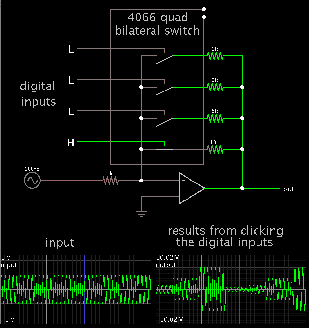
I am here again with a new idea of making a digital volume control on the basis of very basic laboratory instrument we were using named "post office box" in physics laboratory

url.jpg

Well coming to the point here i am posting a diagram contaning the basic circuit with the truth table below showing the triggering status so as to increase or decrease the volume (not showing all the lines)

Volume control project.jpg

I made it on express pcb . .

Is it a sucessfull model ? what would be the value of triggering resistor Rt approx . . ?

please reply . . thankssssss

Too tell me please if this will damage the amplifier or other musical instrument or music players unit ???
 

I don't believe that the "post office box" uses bipolar transistor switches.

It's also a bad idea to use them for audio signal switching, particularly in the suggested configuration:

- to avoid distortions, the audio voltage across a transistor must not exceed a few 10 millivolts.
- according to the series connection, there's no suitable DC path for the controlling base current
- the base current will superimpose large DC voltages to the audio signal


sir i told its the post office box which is only a base i mean to say its function containing tap keys in/out thats it
Its only the base not the exact function application

so what about if i use a relay or an LDR or a photodiode like arrangments in place of transistors ????????

please reply

- - - Updated - - -

I don't believe that the "post office box" uses bipolar transistor switches.

It's also a bad idea to use them for audio signal switching, particularly in the suggested configuration:

- to avoid distortions, the audio voltage across a transistor must not exceed a few 10 millivolts.
- according to the series connection, there's no suitable DC path for the controlling base current
- the base current will superimpose large DC voltages to the audio signal


sir i told its the post office box which is only a base i mean to say its function containing tap keys in/out thats it
Its only the base not the exact function application

so what about if i use a relay or an LDR or a photodiode like arrangments in place of transistors ????????

please reply
 

LDR or relays are perfectly suited, also CMOS analog switches or individual JFET or MOSFET with suitable level shift circuits for the control voltage.

You should however consider the intended volume control range. Electronical volume controls are usually implementing a logarithmic (dB linear) attenuator characteristic.
 

Here is a programmable gain op amp (from the Forrest Mims Engineer's Notebook).


Resistor values can be chosen to amplify or attenuate. They can be switched in one at a time, or in parallel.

Any number of switches can be added.
 

LDR or relays are perfectly suited, also CMOS analog switches or individual JFET or MOSFET with suitable level shift circuits for the control voltage.

You should however consider the intended volume control range. Electronical volume controls are usually implementing a logarithmic (dB linear) attenuator characteristic.


ohh kk thats the point hmmm
sir could you please let me have some examples with a circuit diagram about what you are explaining here ??
specially CMOS analog switches & implementation of a logarithmic (dB linear) attenuator characteristic.

thanks

- - - Updated - - -

Here is a programmable gain op amp (from the Forrest Mims Engineer's Notebook).


Resistor values can be chosen to amplify or attenuate. They can be switched in one at a time, or in parallel.

Any number of switches can be added.


ohh thats a new idea here :)
its nice one sir

could you please tell me that if this 4 switches can make 16 combinations which can form the required levels or equivalent levels of what we get in manual volume controls ???????????

please tell

- - - Updated - - -

ohh kk thats the point hmmm
sir could you please let me have some examples with a circuit diagram about what you are explaining here ??
specially CMOS analog switches & implementation of a logarithmic (dB linear) attenuator characteristic.

thanks

- - - Updated - - -


ohh thats a new idea here :)
its nice one sir

could you please tell me that if this 4 switches can make 16 combinations which can form the required levels or equivalent levels of what we get in manual volume controls ???????????

please tell


also tell which op amp number should i use . .thanks
 

ohh thats a new idea here :)
its nice one sir

could you please tell me that if this 4 switches can make 16 combinations which can form the required levels or equivalent levels of what we get in manual volume controls ???????????

Yes, you can create 16 combinations from 4 switches. Or 64 combinations from 8 switches. Etc.

However since the resistors will be combined in parallel, it is tricky to figure out what values to use, and which ones to switch on, to obtain the range you wish, and in increments you wish.

The op amp can probably be any one of your choosing.
 

so may i go for 741 or 386 or 810 ??
 

so may i go for 741 or 386 or 810 ??

I don't think it is crucial which one you use.
However the 386 may not be suitable. The applications I'm looking at do not show a typical feedback resistor to the inverting input. The 386 does gain adjustment in a different manner.

This is where your own experimentation will tell you more than any expert can.


hmm ya right

well for a CD4066 is there any polarity for switches when we connect the required switching terminals ???????????????
 

hmm ya right

well for a CD4066 is there any polarity for switches when we connect the required switching terminals ???????????????

If you mean the analog signal... it can go either direction (positive or negative). The input and output terminals are reversible. In that manner it's as convenient to use as if it were a relay.

If you mean the gate (or control) signal... It is digital. You should apply either zero V or supply V.
 

If you mean the analog signal... it can go either direction (positive or negative). The input and output terminals are reversible. In that manner it's as convenient to use as if it were a relay.

If you mean the gate (or control) signal... It is digital. You should apply either zero V or supply V.


o no no no not gate terminal , i know about that

i am just asking about the switching terminals for the analog input (sound signals) . .
 

Status
Not open for further replies.

Part and Inventory Search

Welcome to EDABoard.com

Sponsor

Back
Top