Continue to Site

Welcome to EDAboard.com

Welcome to our site! EDAboard.com is an international Electronics Discussion Forum focused on EDA software, circuits, schematics, books, theory, papers, asic, pld, 8051, DSP, Network, RF, Analog Design, PCB, Service Manuals... and a whole lot more! To participate you need to register. Registration is free. Click here to register now.

EUSART Data is not showing as expected

Status
Not open for further replies.

Djsarkar

Member level 3
Joined
Jul 27, 2020
Messages
55
Helped
0
Reputation
0
Reaction score
1
Trophy points
8
Activity points
301
Hi

I have PIC18F45K80. I am using MPLABX 5.40 and XC8 2.30. I want to send data from PIC to my laptop

Here is my program
C:
#define _XTAL_FREQ 8000000
#include <xc.h>
// PIC18F45K80 Configuration Bit Settings
// 'C' source line config statements
// CONFIG1L
#pragma config RETEN = OFF      // VREG Sleep Enable bit (Ultra low-power regulator is Disabled (Controlled by REGSLP bit))
#pragma config INTOSCSEL = HIGH // LF-INTOSC Low-power Enable bit (LF-INTOSC in High-power mode during Sleep)
#pragma config SOSCSEL = HIGH   // SOSC Power Selection and mode Configuration bits (High Power SOSC circuit selected)
#pragma config XINST = OFF       // Extended Instruction Set (Enabled)
// CONFIG1H
#pragma config FOSC = INTIO2    // Oscillator (Internal RC oscillator)
#pragma config PLLCFG = OFF     // PLL x4 Enable bit (Disabled)
#pragma config FCMEN = OFF      // Fail-Safe Clock Monitor (Disabled)
#pragma config IESO = OFF       // Internal External Oscillator Switch Over Mode (Disabled)
// CONFIG2L
#pragma config PWRTEN = OFF     // Power Up Timer (Disabled)
#pragma config BOREN = SBORDIS  // Brown Out Detect (Enabled in hardware, SBOREN disabled)
#pragma config BORV = 3         // Brown-out Reset Voltage bits (1.8V)
#pragma config BORPWR = ZPBORMV // BORMV Power level (ZPBORMV instead of BORMV is selected)
// CONFIG2H
#pragma config WDTEN = OFF      // Watchdog Timer (WDT disabled in hardware; SWDTEN bit disabled)
#pragma config WDTPS = 1048576  // Watchdog Postscaler (1:1048576)
// CONFIG3H
#pragma config CANMX = PORTB    // ECAN Mux bit (ECAN TX and RX pins are located on RB2 and RB3, respectively)
#pragma config MSSPMSK = MSK7   // MSSP address masking (7 Bit address masking mode)
#pragma config MCLRE = ON       // Master Clear Enable (MCLR Enabled, RE3 Disabled)
// CONFIG4L
#pragma config STVREN = ON      // Stack Overflow Reset (Enabled)
#pragma config BBSIZ = BB2K     // Boot Block Size (2K word Boot Block size)
// CONFIG5L
#pragma config CP0 = OFF        // Code Protect 00800-01FFF (Disabled)
#pragma config CP1 = OFF        // Code Protect 02000-03FFF (Disabled)
#pragma config CP2 = OFF        // Code Protect 04000-05FFF (Disabled)
#pragma config CP3 = OFF        // Code Protect 06000-07FFF (Disabled)
// CONFIG5H
#pragma config CPB = OFF        // Code Protect Boot (Disabled)
#pragma config CPD = OFF        // Data EE Read Protect (Disabled)
// CONFIG6L
#pragma config WRT0 = OFF       // Table Write Protect 00800-01FFF (Disabled)
#pragma config WRT1 = OFF       // Table Write Protect 02000-03FFF (Disabled)
#pragma config WRT2 = OFF       // Table Write Protect 04000-05FFF (Disabled)
#pragma config WRT3 = OFF       // Table Write Protect 06000-07FFF (Disabled)
// CONFIG6H
#pragma config WRTC = OFF       // Config. Write Protect (Disabled)
#pragma config WRTB = OFF       // Table Write Protect Boot (Disabled)
#pragma config WRTD = OFF       // Data EE Write Protect (Disabled)
// CONFIG7L
#pragma config EBTR0 = OFF      // Table Read Protect 00800-01FFF (Disabled)
#pragma config EBTR1 = OFF      // Table Read Protect 02000-03FFF (Disabled)
#pragma config EBTR2 = OFF      // Table Read Protect 04000-05FFF (Disabled)
#pragma config EBTR3 = OFF      // Table Read Protect 06000-07FFF (Disabled)
// CONFIG7H
#pragma config EBTRB = OFF      // Table Read Protect Boot (Disabled)
void Port_Initialized (void)
{
    LATA = LATB = LATC = LATD = LATE =  0;
    TRISA = 0b0000000;// all are output, Unused
    TRISB = 0b0000000;// all are output, Unused
    TRISC = 0b1000000; // TX Pin set as output, RX Pin set as input
    TRISD = 0b0000000;//all are output, Unused
    TRISE = 0b0000000;// All are output, Unused

    ANCON0 = 0; // digital port
    ANCON1 = 0; // digital port
    CM1CON = 0; // Comparator off
    CM2CON = 0; // Comparator off
    ADCON0 = 0; // A/D conversion Disabled
}

void send(char message)
{
    while(TXIF==0);  // Wait till the transmitter register becomes empty
    TXREG = message;
}
void string(char *p)
{
   while(*p != '\0') {
     send(*p);
     __delay_ms(1);
     p++;
   }
}
void Uart_Initialized(void)
{
    //TXSTAx TRANSMIT STATUS AND CONTROL REGISTER

   TXSTAbits.CSRC = 0; //: Don?t care.
   TXSTAbits.TX9 = 0; //Selects 8-bit transmissionbit
   TXSTAbits.TXEN = 1; // Transmit Enable
   TXSTAbits.SYNC  = 0;   // Asynchronous mode
   TXSTAbits.SENDB = 0;
   TXSTAbits.BRGH =  1;   //  High speed mode

   TXSTAbits.TX9D = 0;
   //RCSTAx: RECEIVE STATUS AND CONTROL REGISTER
   RCSTAbits.SPEN  = 1 ;   //Serial port enabled
   RCSTAbits.RX9 = 0; //Selects 8-bit reception
   RCSTAbits.SREN  = 1 ;//Don?t care.
   RCSTAbits.CREN  = 1 ;// Enables receiver
   RCSTAbits.ADDEN = 0; //
   RCSTAbits.FERR  = 0 ;// No framing error
   RCSTAbits.OERR  = 1 ;   // Overrun error
   RCSTAbits.RX9D   = 0 ;   //Selects 8-bit reception

   SPBRG = 51;

}

void main(void)
{
   char message[]= {"Hello world"};
   Port_Initialized ();
   Uart_Initialized ();
   string(message);

    while (1)
    {
    
    
    }
}


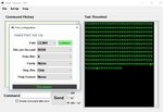
when I run code I am getting garbage value on hyper terminal.

Hyper terminal settings

baud rate 9600
Data bit 8
parity none
stop bit 1


In schematic, connections between the PIC and the MAX232 swapped.
but expert suggested following connection
The PIC TX should connect to T1IN (pin 11)
and PIC RX should connect to R1OUT (pin 12)

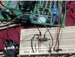
so I have developed my own circuit
Red 5V
Black gnd
gray gnd
Blue Input from RC7
Yellow output from maxrs232N

When I see data with developed circuit I don't get any value on hyper terminal

Any help would be appreciated
 

Attachments

  • board.jpg
    board.jpg
    73.9 KB · Views: 110
  • Ucoonection.jpg
    Ucoonection.jpg
    150.2 KB · Views: 106
  • PIC DEV BRD SCHEMATIC.pdf
    82.4 KB · Views: 101
  • de9.jpg
    de9.jpg
    208.5 KB · Views: 112
Last edited:

That's it - I have had enough :mad:

I hereby declare you dishonest, duplicitous troll

You have had a ton of help on Microchip forum on this exact topic, a ton of help on other topics spread around multiple forums.

And the reward we get.... the good help given is ignored and the same question asked again on another forum.

I could have helped hugely once my PIC18F45K80 chip arrived, but am now far too angry and disappointed to want to help.

Why don't you come clean and give links to all of your other posts on all of the other forums. Others (not me - I am out) can then see a full picture, not breadcrumbs.

Goodbye and good riddance

EDIT: disclaimer - my (mean) opinion only - happy to be corrected if you think I am being unfair
 
Last edited:

That's it - I have had enough :mad:

I hereby declare you dishonest, duplicitous troll

You have had a ton of help on Microchip forum on this exact topic, a ton of help on other topics spread around multiple forums.

And the reward we get.... the good help given is ignored and the same question asked again on another forum.

Hi hexreader

I don't think there is wrong if my problem is not solved on one forum and I ask it on another forum. I had started thread on microchip forum a week ago. I have followed suggestions but I'm still struggling.

If anyone feels that I am really making effort, then someone will definitely help me.

I am a student and i just started learning a few months ago. And I am trying to give my best
 

" I don't think there is wrong if my problem is not solved on one forum and I ask it on another forum "

Nothing wrong as long as you are honest and provide a link to the old post on the other forum. IMHO

Disclaimer - my world view only - happy to be corrected

EDIT: Provide a link on both forums, not just one - IMHO

EDIT2: others on other forums/posts have shown frustration with you too - it is not just me
 
Last edited:

Tell us what the BRG16 bit is set to. It selects either an 8-bit baud rate generator or a 16-bit baud generator, if using 16-bits you might need to adjust the high bits to get the right baud rate.

The fact that you are getting some output at all means you have the UART working but possibly with the wrong configuration.

Important: you have no decoupling capacitor across the MAX232 supply pins. It is essential you add one, especially using breadboard construction. Try wiring a 10uF capacitor directly across pins 15 and 16.

Looking at the photographs of the breadboard, I can only see two wires going to the D socket, I presume one of them is ground (D pin 5) and you are not using the receive path at all, is that correct?

The main board already has an RS232 interface on it, why don't you use it?

Brian.
 
hello,
What are the capacitors values ( C104 on schematic) around Max232 ,
seems to be low value ceramique capacitor on breadboard .. ?
maybe need 1µF to 10µF .. depend of the exact reference of MAX232 ..
 

Tell us what the BRG16 bit is set to. It selects either an 8-bit baud rate generator or a 16-bit baud generator, if using 16-bits you might need to adjust the high bits to get the right baud rate

The fact that you are getting some output at all means you have the UART working but possibly with the wrong configuration.

Brian.

BRG16 = 1 // 16-bit Baud Rate Generator – SPBRGHx and SPBRGx
When I set BRG16, 16-bit baud generator( 16 bit register).

(BRGH = 0, BRG16 = 1)
For a device with FOSC of 8 MHz, desired baud rate of 9600, Asynchronous mode, and 8-bit BRG:
Desired Baud Rate = FOSC/(64 ([SPBRGHx:SPBRGx] + 1)) Solving for SPBRGHx:SPBRGx:
X = ((FOSC/Desired Baud Rate)/64) – 1
= ((8000000/9600)/16 -1
= 833.33/16-1
= 52-1 = 51

The main board already has an RS232 interface on it, why don't you use it?
Brian.
following information is given in user manual

SERIAL COMMUNICATION :
CONNECT THE TX TO RX AND RX TO TX
CONNECT THROUGH HYPER TERMINAL - 9600 BAUDRATE
MESSAGE WILL APPEAR IN HYPER TERMINAL SCREEN

Expert said post #15, #26
the schematic shows the PIC's TX and RX pins swapped. If that is how your board is really wired, it is a fault in their design.
https://www.microchip.com/forums/m1154362.aspx
That's why started to make my own circuit
 
Last edited:

I would imagine that board makes the TX and RX pins to the internal MAX232 available for you to link to the appropriate pins on the PIC. If that is the case, just reverse the links between the TX/RX pins at one end and the problem is solved.

Don't confuse BRG16 with SPBRGH and SPBRG. BRG16 is a single bit but SPBRGH and SPBRG are complete registers. If you enable 16 bit mode with the BRG16 bit you have to load both the SPBRGH and SPBRG registers with a value. In your case with an 8MHz crystal SPBRGH = 0 and SPBRG = 51, I do not see any settings for any of those registers in your code.

Brian.
 
Hi,
I don't think there is wrong if my problem is not solved on one forum and I ask it on another forum. I had started thread on microchip forum a week ago. I have followed suggestions but I'm still struggling.

If anyone feels that I am really making effort, then someone will definitely help me.

I am a student and i just started learning a few months ago. And I am trying to give my best
Just a short comment on this:
I see you ask questions. A lot of questions, soem repeated, some parallel on other forum.
* but rarely answer our questions
* and rarely follow our recommendations

Thus my recommendation:
* focus on one forum. Focus on one member (here I see good communication between you and Brian). strictly follow the member´s recommendations and feed back the results. Be patient. Be thankful to motivate members to support you.

Otherwise ... it seems you more confuse yourself than make progress.

Klaus
 
Hi,
I did program and test code from the same original poster in Microchip forum.
Code seem identical to what is shown in message #1
and did function with correct frequency on PIC18F26K80. Bit time 104 microsecond.

BRG16 bit was not set by software, BRG16 is 0 from reset default.

I have followed this poster in Microchip Forum, and now here,
it seem to be hardware wiring problem.

Mysil
 
I do not see any settings for any of those registers in your code.

Brian.

Please see code in post #1 Uart_Initialized function. last line is SPBRG = 51;

I did following modification and tried code
SPBRG1 = 51;
SPBRGH1 = 0;

But still I am not getting correct data on terminal

edit spelling
--- Updated ---

Hi, it seem to be hardware wiring problem.

if the problem is with wiring so can we use module in 8051 development board. all the connection is there

8051 Usart.jpg


Edit : trying to find schematic diagram of board connection
 
Last edited:

Without the capacitors across +5V and GND near the MAX232 it will not work, regardless of what software you use.

Please try this:
1. Use the RS232 socket on the board, not the one you have made.

2. Link the test pin marked TX to RC6

3. Link the test pin marked RX to RC7

4. Change the line "#pragma config FOSC = INTIO2 // Oscillator (Internal RC oscillator)" to
#pragma config FOSC = HS // crystal oscillator

5. Then change the line "#define _XTAL_FREQ 8000000" so the frequency is the same as the one one the crystal on the board.

Let me know what happens.

Brian.
 
The "other" thread is at https://www.microchip.com/forums/m1154362.aspx
I have spent a lot of time trying to help this user. I agree he has a hardware connection problem, but he seems to have a very short attention span, and ignores half of what he is told.
Hi ric , I have already provided thread link and mention your post in post #8
--- Updated ---

Without the capacitors across +5V and GND near the MAX232 it will not work, regardless of what software you use.

Please try this:
1. Use the RS232 socket on the board, not the one you have made.

5. Then change the line "#define _XTAL_FREQ 8000000" so the frequency is the same as the one one the crystal on the board.

Let me know what happens.

Brian.
1. Do you mean the socket on the PIC board or socket on 8051? I assume socket on PIC board

2 this line gives error #pragma config FOSC = HS // crystal oscillator
uart.c:15:: error: (1363) unknown configuration setting/register (FOSC = HS)

3. #define _XTAL_FREQ 8000000
What to change in this line ?
 
Last edited:

1. Do you mean the socket on the PIC board or socket on 8051? I assume socket on PIC board
He means the socket on the PIC board, and just swap the inputs to the on-board MAX232 chip, which is what I suggested ages ago.

2 this line gives error #pragma config FOSC = HS // crystal oscillator
uart.c:15:: error: (1363) unknown configuration setting/register (FOSC = HS)

That needs to be "FOSC=HS1" if the crystal is 4-16MHz, or "FOSC=HS2" if it is 16-25MHz.

3. #define _XTAL_FREQ 8000000
What to change in this line ?
The number should be the crystal frequency in Hertz.
 
He means the socket on the PIC board, and just swap the inputs to the on-board MAX232 chip, which is what I suggested ages ago.
That needs to be "FOSC=HS1" if the crystal is 4-16MHz, or "FOSC=HS2" if it is 16-25MHz.
The number should be the crystal frequency in Hertz.

I am running following program but problem is same

C:
#define _XTAL_FREQ 8000000


#include <xc.h>
// PIC18F45K80 Configuration Bit Settings
// 'C' source line config statements
// CONFIG1L
#pragma config RETEN = OFF      // VREG Sleep Enable bit (Ultra low-power regulator is Disabled (Controlled by REGSLP bit))
#pragma config INTOSCSEL = HIGH // LF-INTOSC Low-power Enable bit (LF-INTOSC in High-power mode during Sleep)
#pragma config SOSCSEL = HIGH   // SOSC Power Selection and mode Configuration bits (High Power SOSC circuit selected)
#pragma config XINST = OFF       // Extended Instruction Set (Enabled)
// CONFIG1H
//#pragma config FOSC = INTIO2    // Oscillator (Internal RC oscillator)
#pragma config FOSC = HS1 // crystal oscillator

#define _XTAL_FREQ 8000000


#pragma config PLLCFG = OFF     // PLL x4 Enable bit (Disabled)
#pragma config FCMEN = OFF      // Fail-Safe Clock Monitor (Disabled)
#pragma config IESO = OFF       // Internal External Oscillator Switch Over Mode (Disabled)
// CONFIG2L
#pragma config PWRTEN = OFF     // Power Up Timer (Disabled)
#pragma config BOREN = SBORDIS  // Brown Out Detect (Enabled in hardware, SBOREN disabled)
#pragma config BORV = 3         // Brown-out Reset Voltage bits (1.8V)
#pragma config BORPWR = ZPBORMV // BORMV Power level (ZPBORMV instead of BORMV is selected)
// CONFIG2H
#pragma config WDTEN = OFF      // Watchdog Timer (WDT disabled in hardware; SWDTEN bit disabled)
#pragma config WDTPS = 1048576  // Watchdog Postscaler (1:1048576)
// CONFIG3H
#pragma config CANMX = PORTB    // ECAN Mux bit (ECAN TX and RX pins are located on RB2 and RB3, respectively)
#pragma config MSSPMSK = MSK7   // MSSP address masking (7 Bit address masking mode)
#pragma config MCLRE = ON       // Master Clear Enable (MCLR Enabled, RE3 Disabled)
// CONFIG4L
#pragma config STVREN = ON      // Stack Overflow Reset (Enabled)
#pragma config BBSIZ = BB2K     // Boot Block Size (2K word Boot Block size)
// CONFIG5L
#pragma config CP0 = OFF        // Code Protect 00800-01FFF (Disabled)
#pragma config CP1 = OFF        // Code Protect 02000-03FFF (Disabled)
#pragma config CP2 = OFF        // Code Protect 04000-05FFF (Disabled)
#pragma config CP3 = OFF        // Code Protect 06000-07FFF (Disabled)
// CONFIG5H
#pragma config CPB = OFF        // Code Protect Boot (Disabled)
#pragma config CPD = OFF        // Data EE Read Protect (Disabled)
// CONFIG6L
#pragma config WRT0 = OFF       // Table Write Protect 00800-01FFF (Disabled)
#pragma config WRT1 = OFF       // Table Write Protect 02000-03FFF (Disabled)
#pragma config WRT2 = OFF       // Table Write Protect 04000-05FFF (Disabled)
#pragma config WRT3 = OFF       // Table Write Protect 06000-07FFF (Disabled)
// CONFIG6H
#pragma config WRTC = OFF       // Config. Write Protect (Disabled)
#pragma config WRTB = OFF       // Table Write Protect Boot (Disabled)
#pragma config WRTD = OFF       // Data EE Write Protect (Disabled)
// CONFIG7L
#pragma config EBTR0 = OFF      // Table Read Protect 00800-01FFF (Disabled)
#pragma config EBTR1 = OFF      // Table Read Protect 02000-03FFF (Disabled)
#pragma config EBTR2 = OFF      // Table Read Protect 04000-05FFF (Disabled)
#pragma config EBTR3 = OFF      // Table Read Protect 06000-07FFF (Disabled)
// CONFIG7H
#pragma config EBTRB = OFF      // Table Read Protect Boot (Disabled)
void Port_Initialized (void)
{
    LATA = LATB = LATC = LATD = LATE =  0;
    TRISA = 0b0000000;// all are output, Unused
    TRISB = 0b0000000;// all are output, Unused
    TRISC = 0b1000000; // TX Pin set as output, RX Pin set as input
    TRISD = 0b0000000;//all are output, Unused
    TRISE = 0b0000000;// All are output, Unused

    ANCON0 = 0; // digital port
    ANCON1 = 0; // digital port
    CM1CON = 0; // Comparator off
    CM2CON = 0; // Comparator off
    ADCON0 = 0; // A/D conversion Disabled
}
  
void send(char message)
{
    while(TXIF==0);  // Wait till the transmitter register becomes empty
    TXREG = message; 
}
void string(char *p)
{
   while(*p != '\0') {
     send(*p);
     __delay_ms(1);
     p++;
   }
}
void Uart_Initialized(void)
{
    //TXSTAx TRANSMIT STATUS AND CONTROL REGISTER
    
    OSCCON = 0x60;
  
   TXSTAbits.CSRC = 0; //: Don?t care.
   TXSTAbits.TX9 = 0; //Selects 8-bit transmissionbit
   TXSTAbits.TXEN = 1; // Transmit Enable
   TXSTAbits.SYNC  = 0;   // Asynchronous mode
   TXSTAbits.SENDB = 0;
   TXSTAbits.BRGH =  1;   //  High speed mode
 
   TXSTAbits.TX9D = 0;
   //RCSTAx: RECEIVE STATUS AND CONTROL REGISTER
   RCSTAbits.SPEN  = 1 ;   //Serial port enabled
   RCSTAbits.RX9 = 0; //Selects 8-bit reception
   RCSTAbits.SREN  = 1 ;//Don?t care.
   RCSTAbits.CREN  = 1 ;// Enables receiver
   RCSTAbits.ADDEN = 0; //
   RCSTAbits.FERR  = 0 ;// No framing error
   RCSTAbits.OERR  = 1 ;   // Overrun error
   RCSTAbits.RX9D   = 0 ;   //Selects 8-bit reception 
 
   SPBRG1 = 51;
  
   SPBRGH1 = 0;
 
}

void main(void)
{
   char message[]= {"H"};
   Port_Initialized ();
   Uart_Initialized ();
   string(message);
 
    while (1)
    {
      
      
    }
}
 

What is the frequency of the crystal on that board?
You have not changed the number in the _XTAL_FREQ from 8000000.

Are you plugging your USB-RS232 adaptor directly into the DE-9 connector on the board, or through a cable?
 

What is the frequency of the crystal on that board?
You have not changed the number in the _XTAL_FREQ from 8000000.

Are you plugging your USB-RS232 adaptor directly into the DE-9 connector on the board, or through a cable?

I have 20 MHZ externa crystal

I am connecting USB-RS232 adaptor directly through a cable

C:
#define _XTAL_FREQ 20000000


#include <xc.h>
// PIC18F45K80 Configuration Bit Settings
// 'C' source line config statements
// CONFIG1L
#pragma config RETEN = OFF      // VREG Sleep Enable bit (Ultra low-power regulator is Disabled (Controlled by REGSLP bit))
#pragma config INTOSCSEL = HIGH // LF-INTOSC Low-power Enable bit (LF-INTOSC in High-power mode during Sleep)
#pragma config SOSCSEL = HIGH   // SOSC Power Selection and mode Configuration bits (High Power SOSC circuit selected)
#pragma config XINST = OFF       // Extended Instruction Set (Enabled)
// CONFIG1H
//#pragma config FOSC = INTIO2    // Oscillator (Internal RC oscillator)
#pragma config FOSC = HS2 // crystal oscillator


#pragma config PLLCFG = OFF     // PLL x4 Enable bit (Disabled)
#pragma config FCMEN = OFF      // Fail-Safe Clock Monitor (Disabled)
#pragma config IESO = OFF       // Internal External Oscillator Switch Over Mode (Disabled)
// CONFIG2L
#pragma config PWRTEN = OFF     // Power Up Timer (Disabled)
#pragma config BOREN = SBORDIS  // Brown Out Detect (Enabled in hardware, SBOREN disabled)
#pragma config BORV = 3         // Brown-out Reset Voltage bits (1.8V)
#pragma config BORPWR = ZPBORMV // BORMV Power level (ZPBORMV instead of BORMV is selected)
// CONFIG2H
#pragma config WDTEN = OFF      // Watchdog Timer (WDT disabled in hardware; SWDTEN bit disabled)
#pragma config WDTPS = 1048576  // Watchdog Postscaler (1:1048576)
// CONFIG3H
#pragma config CANMX = PORTB    // ECAN Mux bit (ECAN TX and RX pins are located on RB2 and RB3, respectively)
#pragma config MSSPMSK = MSK7   // MSSP address masking (7 Bit address masking mode)
#pragma config MCLRE = ON       // Master Clear Enable (MCLR Enabled, RE3 Disabled)
// CONFIG4L
#pragma config STVREN = ON      // Stack Overflow Reset (Enabled)
#pragma config BBSIZ = BB2K     // Boot Block Size (2K word Boot Block size)
// CONFIG5L
#pragma config CP0 = OFF        // Code Protect 00800-01FFF (Disabled)
#pragma config CP1 = OFF        // Code Protect 02000-03FFF (Disabled)
#pragma config CP2 = OFF        // Code Protect 04000-05FFF (Disabled)
#pragma config CP3 = OFF        // Code Protect 06000-07FFF (Disabled)
// CONFIG5H
#pragma config CPB = OFF        // Code Protect Boot (Disabled)
#pragma config CPD = OFF        // Data EE Read Protect (Disabled)
// CONFIG6L
#pragma config WRT0 = OFF       // Table Write Protect 00800-01FFF (Disabled)
#pragma config WRT1 = OFF       // Table Write Protect 02000-03FFF (Disabled)
#pragma config WRT2 = OFF       // Table Write Protect 04000-05FFF (Disabled)
#pragma config WRT3 = OFF       // Table Write Protect 06000-07FFF (Disabled)
// CONFIG6H
#pragma config WRTC = OFF       // Config. Write Protect (Disabled)
#pragma config WRTB = OFF       // Table Write Protect Boot (Disabled)
#pragma config WRTD = OFF       // Data EE Write Protect (Disabled)
// CONFIG7L
#pragma config EBTR0 = OFF      // Table Read Protect 00800-01FFF (Disabled)
#pragma config EBTR1 = OFF      // Table Read Protect 02000-03FFF (Disabled)
#pragma config EBTR2 = OFF      // Table Read Protect 04000-05FFF (Disabled)
#pragma config EBTR3 = OFF      // Table Read Protect 06000-07FFF (Disabled)
// CONFIG7H
#pragma config EBTRB = OFF      // Table Read Protect Boot (Disabled)
void Port_Initialized (void)
{
    LATA = LATB = LATC = LATD = LATE =  0;
    TRISA = 0b0000000;// all are output, Unused
    TRISB = 0b0000000;// all are output, Unused
    TRISC = 0b1000000; // TX Pin set as output, RX Pin set as input
    TRISD = 0b0000000;//all are output, Unused
    TRISE = 0b0000000;// All are output, Unused

    ANCON0 = 0; // digital port
    ANCON1 = 0; // digital port
    CM1CON = 0; // Comparator off
    CM2CON = 0; // Comparator off
    ADCON0 = 0; // A/D conversion Disabled
}
  
void send(char message)
{
    while(TXIF==0);  // Wait till the transmitter register becomes empty
    TXREG = message; 
}
void string(char *p)
{
   while(*p != '\0') {
     send(*p);
     __delay_ms(1);
     p++;
   }
}
void Uart_Initialized(void)
{
    //TXSTAx TRANSMIT STATUS AND CONTROL REGISTER
    
    OSCCON = 0x60;
  
   TXSTAbits.CSRC = 0; //: Don?t care.
   TXSTAbits.TX9 = 0; //Selects 8-bit transmissionbit
   TXSTAbits.TXEN = 1; // Transmit Enable
   TXSTAbits.SYNC  = 0;   // Asynchronous mode
   TXSTAbits.SENDB = 0;
   TXSTAbits.BRGH =  1;   //  High speed mode
 
   TXSTAbits.TX9D = 0;
   //RCSTAx: RECEIVE STATUS AND CONTROL REGISTER
   RCSTAbits.SPEN  = 1 ;   //Serial port enabled
   RCSTAbits.RX9 = 0; //Selects 8-bit reception
   RCSTAbits.SREN  = 1 ;//Don?t care.
   RCSTAbits.CREN  = 1 ;// Enables receiver
   RCSTAbits.ADDEN = 0; //
   RCSTAbits.FERR  = 0 ;// No framing error
   RCSTAbits.OERR  = 1 ;   // Overrun error
   RCSTAbits.RX9D   = 0 ;   //Selects 8-bit reception 
 
   SPBRG1 = 129;
  
   SPBRGH1 = 0;
 
}

void main(void)
{
   char message[]= {"H"};
   Port_Initialized ();
   Uart_Initialized ();
   string(message);
 
    while (1)
    {
      
      
    }
}
 

Status
Not open for further replies.

Similar threads

Part and Inventory Search

Welcome to EDABoard.com

Sponsor

Back
Top