D.A.(Tony)Stewart
Advanced Member level 7
- Joined
- Sep 26, 2007
- Messages
- 9,021
- Helped
- 1,824
- Reputation
- 3,647
- Reaction score
- 2,206
- Trophy points
- 1,413
- Location
- Richmond Hill, ON, Canada
- Activity points
- 59,642
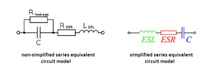
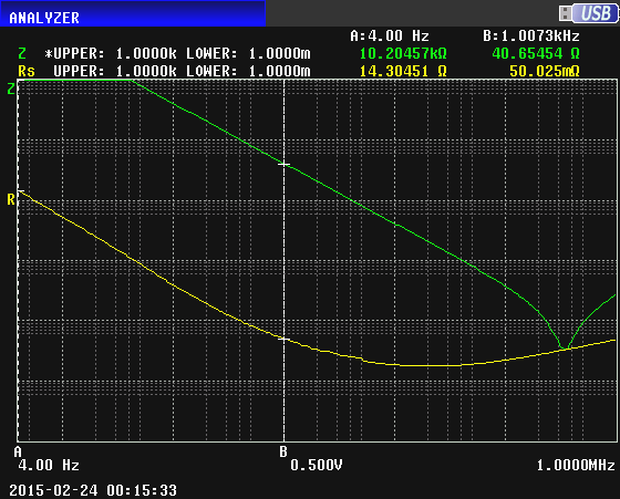
I would like to see how any cap. can suffer from the apparent rise in ESR below 10 Hz or even at 1 Hz.
I always treated it as fixed because it is insignificant , always being <2% of the total impedance.
Unlike at high freq. or square wave voltages or currents , where ESR dissipation is significant.
I highly doubt any cap discharge design at 1hz rate for LEDs is affected by the rise of ESR at 1Hz when the reactance is >50x greater.
i guess for energy storage it means efficiency is limited to 98-99% in low ESR caps due to dielectric loss resistance.