Continue to Site

Welcome to EDAboard.com

Welcome to our site! EDAboard.com is an international Electronics Discussion Forum focused on EDA software, circuits, schematics, books, theory, papers, asic, pld, 8051, DSP, Network, RF, Analog Design, PCB, Service Manuals... and a whole lot more! To participate you need to register. Registration is free. Click here to register now.

ESR meter project from Nuova Elettronica

Status
Not open for further replies.
We can't pinpoint the problem. You have to do that. We only can guide you.
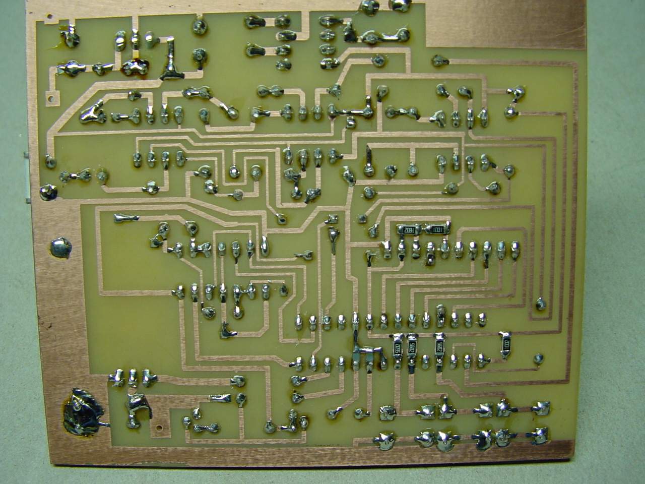
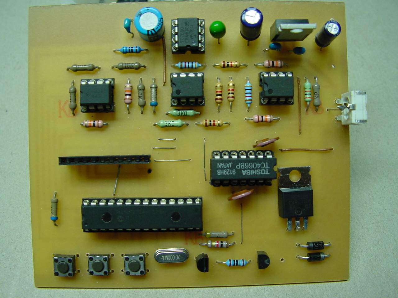
Check the circuit board and the components. Look for shortcuts or discontinued trails, check for +5V and -5V ( in fact is only -4.2V ). Change LM393 and CD4066, swich DA1 with DA2. Make sure to write correct hex for your PIC. Some people use the same hex for PIC876A and PIC873A but others said that the hex is different.
If all is ok than you have to try with other PIC.
 

Have made a new circuit board.
Circuits (including the Pic) replaced and checked voltages.
No success.
As previously described, the display shows only half the resistance value of resistor connected.


---------- Post added at 18:40 ---------- Previous post was at 17:52 ----------

I've corrected the error in R24. -5V are now offering. That it was not.
How high can adjust the correction factor?
 

I'm not familiar with this particular PCB revision design, are you sure there is no any errors in PCB routing?
Ajusment can correct up 2 or even more times discrepancy, but that's not a good sign.
Normally, initial discrepancy shouldn't be more than 10-20% of actual value of the resistor. Let's go through the Setup again to make sure nothing is missing. Here is the author's web site - https://www.rlc-esr.ru/index.php?option=com_content&view=article&id=78&Itemid=95
I'll try my best to help you.
1. Check +5v/-5v Voltages. I saw you did it already...
2. Adjustments:
2.1 Press and hold "+" button, while you power on the meter, short the leads. Meter will go Setup mode.
Ajust R4 to set minimal reading in 1 Ohm channel (but not zero!). 0001...0003 will be enough.
While still holding "+" button, press "Set" button - it will save the settings. Note: you have to use version 1.1 (latest) of the firmware, especially if you use PIC16F876A CPU.
3. Setting up correction factors. There are 3 of them - one for 1 Ohm channel, one for 10 Ohm channel and one for capacitance.
Make sure you use precision (1% or better) inductance-free resitors 1 Ohm, 10 Ohm and capacitor, like 1000 uF with verified (trusted) value. Measure and write down their measured values.
Press and hold "Set" button while power on the meter. It will go to Coefficients correction mode.
Switching between 1 Ohm, 10 Ohms and Cx - button "Set", Saving - same button. Changing values - buttons "+" and "-".
If discrepancy is too big (like 2 times), try to replace TL431 to other maker, preferrably from well-known brands like TI, Fairchild, Motorola. Avoid PL431 - they are not working well in this meter. Check the 10ma current (should be 10 +/-0,5ma),sometimes you may have to change resistor 180 Ohms (or transistor).
Properly ajusted meter will have precision of about 1% and even better. Good luck!
 
Hi to all forum's members.
I built go esr meter,‫‪dip components‬‬ version.I used two lf412 in place to tl082 and a ceramic resonator ZTA 20.00MX+two ceramic capacitors of 22pF,in place to quartz resonator.For the power,to make -5V I used icl7660.I put coefficient 1.050 for 1 ohm and 0.960 for 10 ohm.When I measure 1 ohm resistor I read 0.999-1.004 variable.When I measure 10 ohm resistor I read 10.001 10.015 10.029 variable.After 1 hour I must to change coefficients to reach same values.It is right for you?If I used tl082 and quartz resonator,I could make better accuracy.Thanks in advance.
 

No,that's not right, coefficients should be very stable. I checked settings after 2 years (!) after I made my GO meter, and nothing is changed!
Don't use ceramic resonators - they have much lesser stability comparing to quartz resonators. Also check how stable voltages +/-5V are, ICL7660 is not very best solution in terms of stability (it may lightly increase fluctuations in last digit). If voltage is fluctuating, it can affect results.
LF412 should be OK instead of TL082 (TL072 can be used instead, too).
Check out also transistor VT1 and precision shunt regulator TL431A (VD2). It supposed to be a source of stable current (10 ma), so if that current is changing over time (if TL431a or transistor is "leaky"), it will affect results. Check also, if potentiometer R4 has reliable central conctact - some cheaply made types can be source of problem.
 
Hi!Thanks a lot for reply.
In fact when I measure -5V without load I get -4.99V but with load I get -4.34 so this voltage are not stable.Exactly where can I measure 10mA current on circuit?Which points?
 

10ma.jpgICL7660 is not designed for big load (10ma tops,I think). As for checking 10ma current, here is picture. This is how it should be connected (CPU must be taken out from socket). VT2 should be temporarily disconnected from VT1 as shown.
Increasing value of R2 will reduce output current, decreasing value of R2 will increase current. It would be perfect to have precisely 10ma... but +/- 0,5ma will be OK.
 

Hi!I built a power supply pcb with two batteries,I checked voltages and these are right,then I did measure of current.I connected tester between A733 collectors(disconnected from VT2) and ground and I put R3(RC0 side) to ground.I removed cpu from socket.I measure 0A.Why?
 

Strange... are you sure this no error? This 10ma test was recommended by some guy at Russian forum **broken link removed** (translated), other guys did it, too, so it works... Can you double-check it? I didn't do it personally - my meter didn't have problems.

Also, this meter has a "debug" mode (power on with "+" key pressed). It will show "raw" values - 15 timer readings per 1uF, and both 1 Ohm and 10 Ohms channels in ADC readings (each step = 5V/1024). So you can see in real-time what's going on, it may help to find "leaking" component...
 

Hi,

Which ESR meter do you guys can advise me to build - from the repository created by kripton or other? I'd like to have one of those.
 

Hi!
Now my meter seems to work.I replaced all 1K 10K resistors with others with tolerance 1% and lf412 with tl082.Then I put 3k 30k resistors where required.I welded the probes directly on pcb,because streep line affect measure.Now I measure 0.996-1.002 for 1 ohm and 9.984-10.014 for 10 ohm after some days too.In debug mode I read Cx --- 1 ohm=0879 10 ohm=0811.
For AMSA84 I suggest this meter that work fine,but in circuit if I measure where there are others capacitors in parallel or series the value is distorted and I must unsolder to check components.This seems to me obvious.
 
Last edited:

Hello hugo.

Can you post here the direct link to that ESR meter that you advised?

BTW, about the problem that you mentioned, can you explain a bit more in detail? Just to see if I understood.

Best regards,
AMSA
 

So, is this the best ESR meter? Is it accurate? The capacitance given by the ESR meter is accurate too?

I am asking this because I saw this one:

**broken link removed**

https://vrtp.ru/index.php?act=ST&f=39&t=15087

You can see the video that he made.

What you guys think about this one?
 
Last edited:

Any one have a good source where the circuit of the GO ESR is explained (in English) how it works? Just getting started. Thank you for the help.
 

So, is this the best ESR meter? Is it accurate? The capacitance given by the ESR meter is accurate too?
I am asking this because I saw this one:
**broken link removed**
https://vrtp.ru/index.php?act=ST&f=39&t=15087
You can see the video that he made.
What you guys think about this one?

To tell you "the best" free DIY meter on Internet is RLC-2 **broken link removed** .
But that project is for sure not for beginners :!:
His previous project (same author -GO) was **broken link removed**
Also very advanced meter. And this **broken link removed** was his very first project. Very decent meter.
There are some other his projects **broken link removed**

As for R2-D2 meters, they are all nice and accurate, I've made all of them. But now they are not "the latest" - his newer version recently came out - **broken link removed**
(and I'm one of his co-authors ;-)).
Also, depending on your skills, you may also take a look at other nice projects - **broken link removed**
It may seems tricky because of all those language barriers, but well, I managed to figure out Hungarian project... :-D
 

It really looks nice! Are there any plans to increase the ESR frequency to 100khz or faster?
Nice job!
 

Status
Not open for further replies.

Similar threads

Part and Inventory Search

Welcome to EDABoard.com

Sponsor

Back
Top