Continue to Site

Welcome to EDAboard.com

Welcome to our site! EDAboard.com is an international Electronics Discussion Forum focused on EDA software, circuits, schematics, books, theory, papers, asic, pld, 8051, DSP, Network, RF, Analog Design, PCB, Service Manuals... and a whole lot more! To participate you need to register. Registration is free. Click here to register now.

Error Amplifier Compensation

Status
Not open for further replies.

txbob

Junior Member level 2
Joined
Nov 24, 2008
Messages
23
Helped
0
Reputation
0
Reaction score
0
Trophy points
1,281
Activity points
1,462
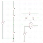
Most of the application notes on Compensation of error amp only talk about restive divider network used for scaling feedback voltage. When differential amplifiers (or single ended amplifiers) are used we need to add a resistor in between Output of the first stage amplifier and inverting pin of the error amplifier (please correct me if I am wrong). Can anyone help me how will we calculate the value of that resistor (R6 in the attached picture)
http://www.irf.com/product-info/datasheets/data/ir3447m.pdf
 

Attachments

  • Typical Ty-2 Feedback Compesation.JPG
    Typical Ty-2 Feedback Compesation.JPG
    107.2 KB · Views: 149
  • Diff amp added.png
    Diff amp added.png
    35.7 KB · Views: 123

R6, in combination with C2 - R4 - C1, create a feedback network. The effect is a low pass filter.

The op amp's input is influenced partly by the input signal, and partly by its own output signal.
There will be a frequency where R6 impedance is equal to the feedback impedance. This is the rolloff frequency.

Choose an R6 value which is much higher than the output impedance of the first op amp.

Then choose the feedback network so it produces the desired rolloff curve.
 
  • Like
Reactions: txbob

    txbob

    Points: 2
    Helpful Answer Positive Rating
Hi,
Thak you for your help
Assuming that both opamps are rail to rail single supply operating at 12v
Is it possible to give me some equations to find out the Roll over frequency and cross over frequency in the case of second picture
thanks
 

The TL072 opamps and nearly all other opamps already have an internal frequency compensation capacitor that allows 100% negative feedback (gain of 1) without oscillation. Then their gain drops as frequencies get higher.
The opamp in the IR3447 needs to operate at a high frequency with plenty of voltage gain so it uses a resistor in series with an external capacitor for compensation.
 
  • Like
Reactions: txbob

    txbob

    Points: 2
    Helpful Answer Positive Rating
Audioguru,
TL072 was only shown for drawing purpose only
Inteneded use of this schematics was in a voltage feed back loop for power supply(buck converter)
I still like to see some euations to find the the roll over frequecy for the second picture

Assuming that both opamps are rail to rail single supply operating at 12v
Is it possible to give me some equations to find out the Roll over frequency and cross over frequency in the case of second picture
thanks
 

If there were only the one capacitor (C2) then you could use the formula for capacitive reactance (below). After that you must adjust the capacitor value, by drawing the parallelogram angles.

X = 1 / ( 2 * Pi * f * C )

The presence of C1 and R4 makes things more complicated, as far as how to calculate the rolloff frequency, and the rolloff rate. Nevertheless these are shaped by the component values, and not so much by the op amp.
 

The transfer function of the type II compensation network is discussed in the linked IRF datasheet on page 29. R6 can be used to set the amplifier gain, but it doesn't affect the frequency characteristic (the poles and zeros).

A more detailed discussion of different error amplifier compensation schemes can be e.g. found in the feedback-loop chapter of the popular text book Pressman, Switching Power Supply Design.

If you compare the voltage divider configuration in your left schematic respectively figure 26 of the IRF datasheet with the right schematic, you'll see that only the top resistor (R1+R2 in your left schematic) influences the AC gain, the bottom resistor sets the DC voltage level but has no effect on the AC gain. This means that for the transfer characteristic, R6 plays the same role as the the top resistor of the voltage divider (R5 in the IRF datasheet).

I'm not sure what you exactly mean with "roll over frequency and cross over frequency". The type II transfer function can be complete characterized by Fz, Fpole and gain of the flat center.

5853974200_1407276461.png
 

Status
Not open for further replies.

Part and Inventory Search

Welcome to EDABoard.com

Sponsor

Back
Top