jegues
Member level 3

- Joined
- May 29, 2011
- Messages
- 58
- Helped
- 0
- Reputation
- 0
- Reaction score
- 0
- Trophy points
- 1,286
- Activity points
- 1,915
Even gents,
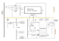
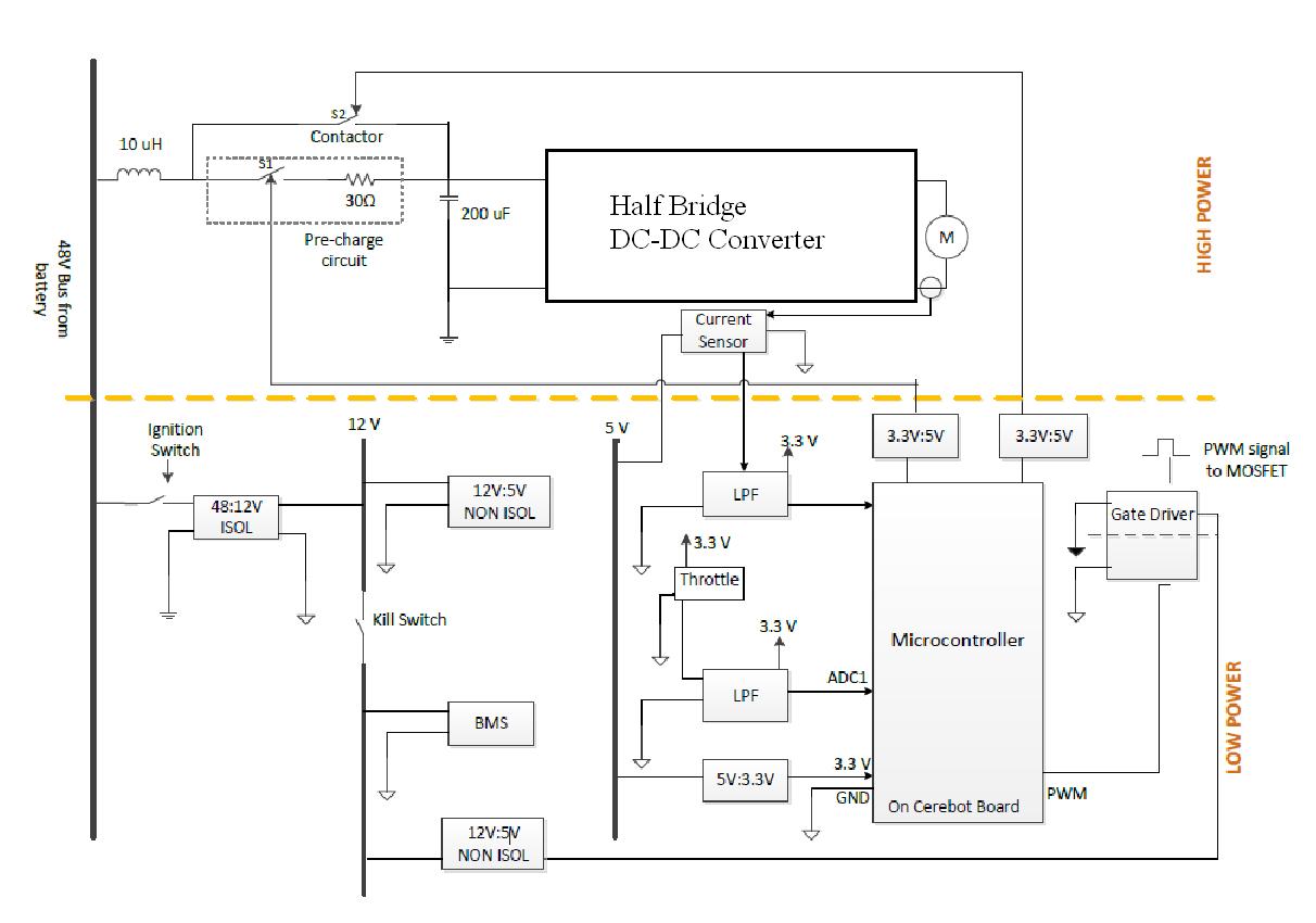
We're working on designing the wiring diagram for our low and high power circuitry for an electric motorcycle.
We're contemplating a configuration like the one attached in the figure below,
I have a couple questions regarding the best way in which to power our electric motorcycles circuitry.
1) First question, is it problematic to place the ignition switch on the bike directly between the high voltage 48V bus and the 48V:12V isolated DC-DC converter? (I've been told we should not be doing this, and I'm not sure why) If so, how can we safely power our circuitry whenever the ignition is turned on?
We do have access to a switched isolated 48:12V DC-DC converter meaning that it can be turned on and off via electrical signal applied to a control pin on the device, but without the 12V supply from the output of the same DC-DC converter we have no means to generate the control signal to the DC-DC converter to turn it on. For example, if the control signal is to be sent from the microcontroller, the microcontroller would need to be powered on, and this wouldn't be the case if the 48:12V DC-DC converter was switched off.
2) Second question, how do I know whether or not a pre-charge circuit is necessary for our DC link capacitor connected across the terminals of our battery bank?
3) Third question, is there any advantage to using a contactor over a solid state relay?
4) Finally, can anyone spot any obvious flaws in the schematic above that we may have missed or not yet have noticed?
Thanks again!

