frusciante89
Newbie level 6
Hi everybody, I have a problem with an electret mic. I searched the forum but i wasn't able to find an answer. I'm pretty new in this field so I hope you can understand my low level... 
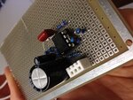
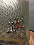
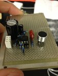
I am design a sound following robot, and I decided to use two electret mics. First problem is how to amplify the signal going to the Arduino. I saw several boards on sparkfun but I want to build my own. I tried to build this one:
https://www.inexglobal.com/downloads/ZX-sound_e.pdf
however, I had to make some modifications due to the available material I had in the lab:
- I used a MC33078 op amp instead of the TLC272
- I used a 10 ohm resistor instead of the 12 ohms (I had none)
- I used only electrolytic caps
This is the arduino code I'm using for the analog signal reading:
/*
AnalogReadSerial
Reads an analog input on pin 0, prints the result to the serial monitor.
Attach the center pin of a potentiometer to pin A0, and the outside pins to +5V and ground.
This example code is in the public domain.
*/
// the setup routine runs once when you press reset:
void setup() {
// initialize serial communication at 9600 bits per second:
Serial.begin(9600);
}
// the loop routine runs over and over again forever:
void loop() {
// read the input on analog pin 0:
int sensorValue = analogRead(A0);
// print out the value you read:
Serial.println(sensorValue);
delay(200); // delay in between reads for stability
}
I tried the circuit and it's not working (gives a reading of 910 no matter how loud I speak into the mic), could it be because of the modifications I made?
I have also a couple of more questions:
what is the best way to process the signal coming from the two mics in order to tell the direction? should I use a volume based detection or a delay based detection?
Thanks for your help,
Andrea


Last edited: