Continue to Site

Welcome to EDAboard.com

Welcome to our site! EDAboard.com is an international Electronics Discussion Forum focused on EDA software, circuits, schematics, books, theory, papers, asic, pld, 8051, DSP, Network, RF, Analog Design, PCB, Service Manuals... and a whole lot more! To participate you need to register. Registration is free. Click here to register now.

Ejection charge circuit question

Status
Not open for further replies.

dk-info

Newbie level 4
Joined
Dec 7, 2011
Messages
6
Helped
1
Reputation
2
Reaction score
1
Trophy points
1,293
Activity points
1,353

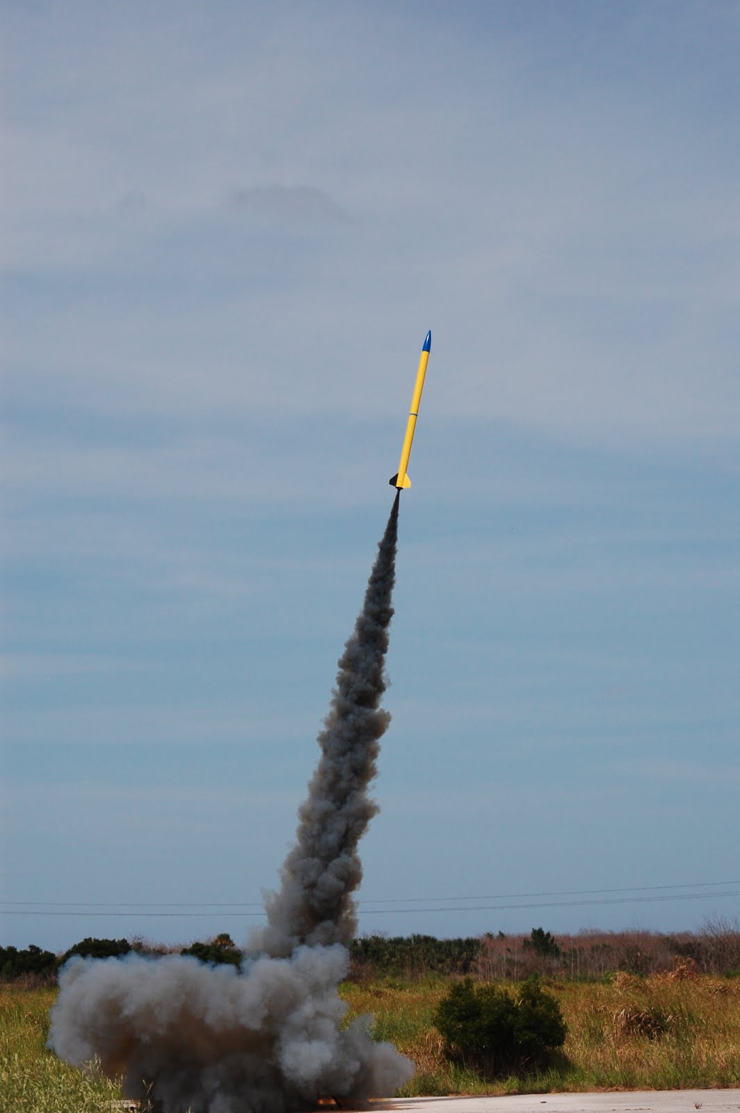
I am designing my own version of a timer designed to eject the parachute of a high powered rocket at a preset time after liftoff.

Using the circuit below as an example, I would like to determine ahead of time if I have continuity with the squib (a nichrome wire dipped in Pyrogen electric match).

With the FET off, I use a low current path (less than 1mA) through the squib, reading the voltage drop across R1 to determine if the wiring is OK.
Nominally the squib is 5Ω to 20Ω, and takes a minimum of 500 mA (usually 750 mA) to fire the squib reliably.


I am worried about the other current paths available, back from the µController, through the +5V to +9V rail... +5V is developed from 9V with a linear regulator
(LM78L05, with a 1uF/16V input, 10uF/6.3V output capacitor)
I do not understand enough of the analog workings of the µController I/O pin (ATMEGA328) to gauge if this is a big concern or is not a concern at all.

I would like to make this circuit as robust as possible; the last thing I want is for the parachute ejection charge to go off in my face when I apply power to the circuit (arm the rocket).

Any comments or ideas would be appreciated.

David W.
Melbourne, Fl.
 

From the diagram it seems 9V is reaching pin 40 via the squib, I dont know if it is needed !!
The role of microcontroller is not clear, only timing can be achieved in a simpler way using NE555 timer or similar approach.
aa CKT.JPG

The regions requiring attention are marked in yellow.
 

You are correct, I neglected to add the divider circuit there.

You are also correct in that a NE555 would be simpler as a single timer circuit but not that easy to adjust in the 0.5 - 240.0 second range I require.
Sometimes I need 65.0 seconds, sometimes I need 75.8 seconds from launch to get the main parachute to open at the appropriate altitude.
Also, the circuitry to detect a launch condition is not there, something a simple NE555 circuit. I admit an Atmega328 is overkill but I happen to have a
a supply of the 44 pin TQFP devices to hand. I communicate with the rocket avionics via a Bluetooth serial link to my cell phone, allowing me to reprogram the
flight profile without having to tear the Electronics bay apart.

Thank you for your kind reply.

David
 

Ok, maybe I don;t get something, but how did you come up with 15 ohm resistor for continuity checking. When power is applied but before microcontroller does anything there is 9V/(5+15R)=0.45 A flowing through squib to GND. I'd aim at something like 1k+1k in series (gives 4.5 mA and ). This gives voltage divider allowing small current to flow through squib to GND while also allowing for measuring voltage with ADC (only 4.5V drop at each of resistors). You also don't need differential measurement across resistor, because on end of it is referenced to GND.

Other thing is that when microcontroller is not powered yet and 9V is present then current will flow from 9V through squib and then through diode clamp protecting microcontroller pin. Allowable current throught that clamp is around 20 mA, and 9V/5R = 1.8A (!) which will literally "go medieval" on your microcontroller. You need to power microcontroller first, and then turn on the 9V supply for the squib. This can be easily done using high-side smart switch or p-mos driven by bjt-based inverter.

This will ensure that no current flows through squib in either direction without you explicitly turning it on.
 

R1 Should have been 15k Ohm, and I also forgot a divider stepping down the 9V into the a/d pin.

I like the high side smart switch idea, it gives me one more way to keep the squib disarmed until the uC is ready to start the timing cycle.
Any ideas on a suitable part number? Depending on the battery chemistry the pulse (< 100 mSec) current could reach 5A.
I do not have any experience with high side FET's, any help would be appreciated.

Thanks for the great feedback,


David
 

Re: Ejection charge circuit question: Circuit clarifications & High Side Switch Quest

Thank you for all the input, here is the corrected circuit.


Does any one have a suggestion for a high side MOSFET that can be controlled by a logic level and handle 5A?

I picked the IPS521G as an example but have no direct experience with a high side switch.

Thank you for your kind input.

David


As for high side switch I'd look at Infineon, IR, Vishay and ST Micro.

Generally in my company we use Infineon most of the time, but that's probably because of other reasons (pricing agreements, automotive certification etc.). U can buy those from Farnell for example (search for 'infineon' and the go to ) IC's -> Drivers and Interfaces -> Mosfet Drivers (i dunno for what reasons those are listed under mosfet drivers anyway...)

As for experience with high side switch: it is not needed. You generally drive it with logic level signal, maybe through some lowpass filter to avoid accidental turn-on from transients.
 

Status
Not open for further replies.

Similar threads

Part and Inventory Search

Welcome to EDABoard.com

Sponsor

Back
Top