Continue to Site

Welcome to EDAboard.com

Welcome to our site! EDAboard.com is an international Electronics Discussion Forum focused on EDA software, circuits, schematics, books, theory, papers, asic, pld, 8051, DSP, Network, RF, Analog Design, PCB, Service Manuals... and a whole lot more! To participate you need to register. Registration is free. Click here to register now.

ECG sensor circuit noise problem

Status
Not open for further replies.

masab_ahmad

Member level 1
Joined
Jul 20, 2010
Messages
32
Helped
0
Reputation
0
Reaction score
0
Trophy points
1,286
Location
Pakistan
Activity points
1,564
Hi!

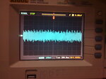
I am making an ECG circuit from this link below, and i've replaced the AD620 with an AD622 instrumentation amplifier. I've also replaced the OP97 op amp with an LM2904. The problem is that i'm not getting any signal from the electrodes and from the output of this circuit (i should have got something). I've attached a photo of the output.

https://www.radiolocman.com/shem/schematics.html?di=47010


These guys (link attached below) also employed the same circuit (and replaced the AD620 with an AD622), and they got a noisy ecg signal straight from their electrodes. So is it possible that my electrodes/skin contacts are faulty?

courses.engr.illinois.edu/ece445/projects/.../project17_presentation.ppt

i also made a similar circuit using a PSoC (which was working according to its author), only to get similar results....
 

Attachments

  • 05082013987.jpg
    05082013987.jpg
    570 KB · Views: 125

Snap a photo or two of the hardware you put together and post them (including power supply and connections), and both sides of any PCBs, plus leads.

How experienced are you, in analog circuit layout? Do you know about needing bypass and decoupling capacitors on every power pin of every chip (which are usually not shown on schematics)? Do you know about minimizing "enclosed loop areas" so you don't make antennas? Do you know about running a separate conductor for each type of ground, and single-point "star" grounding? Do you know about the necessity of RF low-pass filtering for every input, and that everything is an input for RF? Have you heard of common mode and differential mode? Did you use matched resistors for the differential inputs?

Why did you change the types of ICs that were used?
 

Thanks for the reply

I'm quite experienced in analog design :p Those ICs were used to reduce the overall cost of the system.

The problem was solved though. It seems the wire connecting the electrodes to the circuit was picking too much noise (50Hz), so i used a standard oscilloscope probe for connection.

Thanks for the questions you posted above though, i'm gonna try them as well :p
 

The LM2904 is one of the noisiest old opamps ever made. Use a low noise, low input bias voltage opamp instead.

The leads to the electrodes should be shielded audio cable (or scope probe cable) with the shields connected to your circuit's 0V.
 

So which op amp would you prefer? it should be in a dual package, and with a cost similar to the LM2904
 

An LM2904 is very old with poor specs so it is CHEAP. But is has a much wider temperature range than the LM358 which is the same dual opamp for a narrow temperature range (and is even cheaper).

A TL072 is an inexpensive low noise wide bandwidth audio dual opamp that I use frequently. It is available as a single opamp (TL071) and as a quad (TL074).
 

For the leads, I would tend to want to use shielded twisted pair for each lead. That would make them much worse antennas (a good thing). The shield (i.e. the "drain wire") would then be connected to chassis ground, near the input to the box, and connected to nothing on the sensor end. And the two internal wires in the twisted pair would be signal and signal ground, or a differential pair. Either way, they would ONLY connect at the first active amplifier, and NOT to the chassis at the input connector, for example. You would keep them twisted inside the unit, too, ALL the way to the input resistor(s).

If you are getting a lot of 50 Hz, then there is probably space between: 1) the two conductors in each (or at least one) of the input leads, and probably also between 2) the wires of the AC mains pair that connects to the transformer, and between 3) the wires in the pairs from the transformer secondaries. Those pairs must ALL be tightly twisted! And if one of the AC wires runs to a power switch, then always run the other one there, too, and keep them twisted ALL the way to the switch (and fuse) and back. But first try either tightly twisting the input pairs (or use shielded twisted pairs), both inside the box AND outside the box, and see if that might be good enough.
 
Last edited:

The patient's body picks up 50Hz from the air. The instrumentation amplifier removes some of this "common-mode" signal then the opamp inverts it and feeds it to the patient's right leg out-of-phase to the common-mode signal to cancel the interference. The values of the two resistors feeding the opamp must be matched.
The gain of the opamp must be accurate and maybe should be adjusted.
 
Thank you for that explanation!

In that case, would it be even more important to eliminate any lead-related sources of 50 Hz bleed-over? Or would it be less important (cancellable similarly?)? I have no idea of the relative magnitudes, either.

But I guess that question should be moot, at least for the external parts of the leads, since the leads should be shielded. But if the internal wiring wasn't well-dressed, it seems like it could add to the problem.
 

It is best to eliminate as much interference as possible so that the input to the instrumentation amplifier is not overloaded.
 

Status
Not open for further replies.

Similar threads

Part and Inventory Search

Welcome to EDABoard.com

Sponsor

Back
Top